One of the most important elements in electronics systems that require high performance is the thermal interface material (TIM) that bonds the microprocessor to the heat spreader that cools the chip. Microprocessors typically run hot, and will easily overheat and burn out without sufficient heat transfer. The TIM provides efficient thermal conduction to the heat spreader.
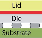
The TIM needs to be free from voids and delaminations that will compromise thermal conduction. The TIM also needs to have a thickness that is within a critical range. If the TIM is too thick or too thin, even over part of the chip, failure is likely. Microprocessors typically use a flip chip design, and the heat spreader (or lid) is attached to the back side of the silicon (figure 1). The TIM described in this article is a resin-based, silver-filled epoxy material that is characterized by very high thermal conductivity. It is somewhat similar to silver-filled epoxies that are used, for example, in die attach applications, but is 3 to 4 times more viscous. The dispensing of the TIM onto the back of the silicon and the placement of the metal heat spreader are critical production steps because the TIM must, after curing, be of the specified thickness and be free from defects. Typically, this type of TIM must be between 50 and 80 microns thick across the entire interface between the heat spreader and the chip. If the TIM is more than 80 microns thick, it will have too much mass, and its thermal conductivity will be reduced, making eventual failure of the chip a likely event. If the TIM is less than 50 microns thick, delaminations are likely to form. In addition to its function as a thermal conductor, the TIM absorbs stresses resulting from the differences in coefficient of thermal expansion between the silicon and the heat spreader. If the TIM is too thin, these stresses will cause the TIM to delaminate from one of the surfaces. Delaminations are efficient thermal insulators, so in this case also thermal conductivity is reduced, and the microprocessor is likely to fail.
How critical the thickness is can be seen by looking at what happens if the TIM thickness is increased. Suppose that a TIM that is normally 75 microns thick is increased to 100 microns by process drift. And suppose that the microprocessor beneath the TIM is putting out 50 watts of heat. Increasing the TIM thickness from 75 microns to 100 microns will increase the temperature of the chip from 0.5 °C to 1.0 °C per watt of output. At the low end of the range, the chip temperature will increase by 25 °C. Since microprocessors tend to run at high temperatures to begin with, this 25 °C increase may be enough to cause failure.
Because process variations can result in microprocessor assemblies that are rejects, it is important to measure the thickness of the TIM as soon as possible after mounting of the heat spreader. Conventionally, these measurements have been made by destructive physical analysis, in which a limited number of microprocessor assemblies removed from production and are cut open so that the thickness of the TIM can be measured. This method takes significant time because the microprocessors must be potted, cut open, and polished to reveal multiple regions of the interface area, since the TIM must meet thickness specifications across the entire bond area. If this analysis shows that there are unacceptable variations in thickness, the time required for analysis may well mean that a significant number of scrap assemblies have been produced in the meantime.
After attachment of the heat spreader, the microprocessors can be inspected more quickly – and non-destructively – by acoustic micro imaging. Acoustic micro imaging is most often used to image hidden internal defects, and it is used in this application to look for delaminations and similar defects in the TIM. But acoustic micro imaging can also, and at the same time, measure the thickness of an internal layer of material, and it is used to measure the thickness of the TIM to ensure that it is within tolerances.
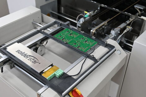
The inspection process is also automated, and uses an acoustic micro imaging system that requires no operator. The microprocessor assemblies are carried in JEDEC-style trays, several assemblies to a tray. The assemblies could be imaged and measured manually, but automated inspection is much faster.
In some applications, the measurement of the thickness of an internal layer by an acoustic micro imaging system is very straightforward. An ultrasonic pulse is beamed into the top surface of the part by the ultrasonic transducer. Ultrasound will be reflected only from material interfaces, and not from the interior of bulk materials. Suppose that the thickness of a silicon die in a plastic package is being measured. The ultrasound travels through the bulk mold compound above the die without returning an echo, because the mold compound is relatively homogeneous. But at the interface between the mold compound and the top of the silicon die an echo is sent back to the transducer. The ultrasonic pulse travels deeper, through the silicon die, and another echo is reflected from the interface between the die and the die attach material below it. The two echoes, one from the mold compound/die interface, and one from the die/die attach interface, arrive at the transducer at different times. Since the speed at which ultrasound travels through the materials involved is known, the time is converted into distance to determine the thickness of the silicon die.
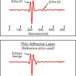
Measuring the thickness of the TIM in the microprocessor assembly follows a somewhat different procedure because of the very small dimension of the TIM thickness. The ultrasound is pulsed through the overlying homogeneous metal heat spreader. Because the heat spreader is metal, a relatively low acoustic frequency is used. Bouncing a relatively low acoustic frequency from two interfaces that are only tens of microns apart means that the two echoes are likely to merge (figure 2). This means that the difference in arrival time, and hence the thickness, cannot be measured directly.
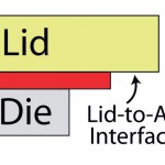
This problem is solved by taking advantage of the fact that the area of the heat spreader is larger than the area of the microprocessor. The heat spreader overhangs the edge of the microprocessor, which means at the underside of the heat spreader at the edge of the assembly is in contact with air (figure 3).
Since the transducer is scanning the entire area of the assembly (partly in order to find delaminations and the like), a reference echo is used from a point where the heat spreader overlies air. This echo gives the time for ultrasound to travel back to the transducer from the bottom of the heat spreader – which is the same as the time from the top of the TIM. The other echo is taken from the interface between the TIM and the die at a specified x-y location, and gives the time of travel from the bottom of the TIM. The heat spreader and die are so flat and parallel that taking the reference echo from a different location does not matter. It is the time difference between these two echoes that is used to accurately measure the TIM thickness. (In other applications where the heat spreader has the same area as the die, and where no overhang is available, advanced software is used to separate the waveforms of the two merged echoes.)
In production, the thickness of the TIM is measured at nine locations across the TIM area. Accept/reject is determined by these nine values, by the average thickness, and by the minimum and maximum thickness values. The measurements are primarily used to spot defect trends, rather than to identify individual problems. The speed and accuracy of the automated acoustic process makes it possible to spot defect trends very quickly and to take corrective action as soon as possible.
EPP Europe 424
zusammenfassung
Vorgestellt wird eine akustische Methode, um die Dicke des Thermal Interface Materials (TIM) in Flip Chips von hochentwickelten Mikroprozessoren zu messen. Das TIM ist eines der wichtigsten Bestandteile in elektronischen Systemen, die hohe Leistung erfordern. Es verbindet den Mikroprozessor mit dem Hitzespreizer, der den Chip kühlt. Ohne ausreichende Hitzeabfuhr laufen Mikroprozessoren heiß, überhitzen und brennen durch.
L’article présente une méthode acoustique permettant de mesurer l’épaisseur du matériau d’interface thermique (Thermal Interface Material – TIM) dans les puces retournées de microprocesseurs sophistiqués. Le TIM est l’un des principaux composants des systèmes électroniques exigeant une puissance élevée. Il lie le microprocesseur avec le disperseur de chaleur, qui refroidit la puce. Si le refroidissement n’est pas suffisant, les microprocesseurs s’échauffent, surchauffent et fondent.
Viene presentato un metodo acustico per la misurazione dello spessore del Thermal Interface Material (TIM) nei Flip Chip dei microprocessori più sviluppati. Il TIM è uno dei componenti più importanti dei sistemi elettronici che richiedono alte prestazioni. Collega il microprocessore al dissipatore che raffredda il chip. Senza un asporto sufficiente di calore, i processori si scaldano, si surriscaldano e si bruciano.
Share:
