Author: Christopher Williams, International Sales Manager, Solderstar
In the rapidly evolving field of electronics manufacturing, reflow ovens have continually undergone development resulting in significant advancements and precise heating profiles for soldering processes. As technology has progressed, process engineers have worked towards optimising these profiles, moving away from inconsistent methods that relied on long ‚fishing wire‘ thermocouples. Today, advanced thermal profilers are available, including micro pass-through units for profile setup, verification fixtures for daily process checks and fully automatic profiling systems, providing real-time temperature graphs and 100% traceability.
A recent development in reflow oven technology is the option to add a vacuum chamber after the peak reflow zone. The vacuum zone results in reduced voiding in the solder joint performed on a convection in-line oven. These types of oven are proving a popular solution for electronic manufacturers, but add an extra process dimension that should be considered and monitored.
Comprehensive thermal profiling
Do we see a setback in thermal profiling? This question prompts us to assess the current situation and examine its implications. Skilled process engineers often rely on their experience with existing reflow ovens to establish a starting point profile that avoids damage to printed circuit boards (PCBs). However, without utilising cutting-edge software that searches millions of reflow oven set-point possibilities to find the best possible process settings, perfecting the profile still demands using a profiler and multiple pass-throughs.
Reflow oven software tools can provide recommended starting points for the oven settings when introducing a new assembly variant to the manufacturing line. This is based upon many years of experience and testing offerings a good starting point. However, the step of the thermal profiling of the actual product should not be skipped and could result is compromised soldering quality. By doing so, engineers have the confidence the process is optimal for the product or confirmed as within specification on an already establish recipe The addition of new advanced process parameters such as vacuum level and hold time, poses a new problem for process engineering.
Innovative solutions
Enhanced temperature data reliability is essential for accurately assessing the process, as inadequate oven profiles can lead to problems like compromised soldering quality, cleaning complications, potential rework expenses or premature component failures. However, creating profiles for every electronic assembly can be time-consuming, particularly when lacking the appropriate tools. There are, however, innovative solutions that accurately measure the entire reflow process. By implementing advanced smart adapters, engineers can utilise diverse sensors in their dataloggers. With zero setup and configuration required, this technology significantly reduces the time and effort traditionally associated with creating assembly profiles.
This flexibility allows for the precise measurement of various process parameters, including vacuum readings, without compromising data quality enabling a comprehensive understanding of the soldering process. Workable carriers are available to facilitate simultaneous profiling of PCBs and the corresponding process, bolstering the arsenal of tools available to electronics engineers.
Process failures through real-world examples
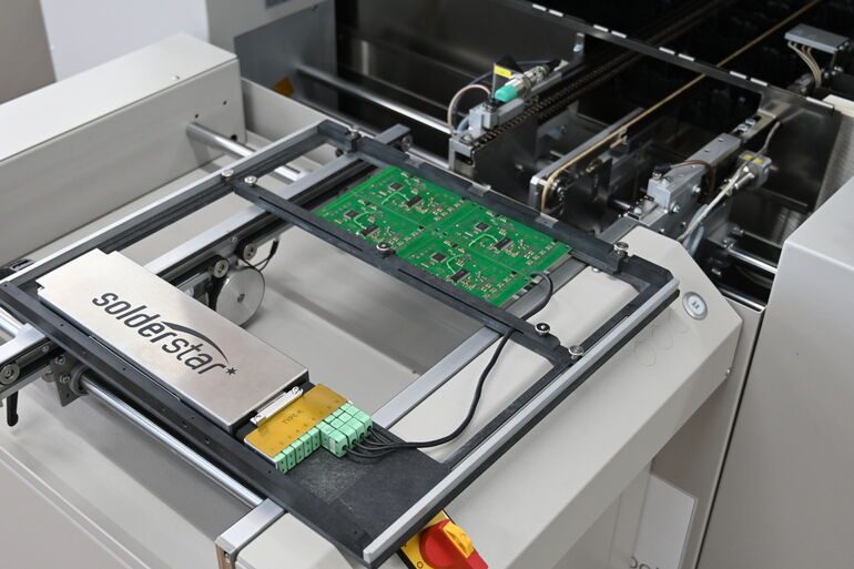
Field tests reveal compelling evidence of the necessity for measuring every aspect of the reflow process. Consider the example of a full-process PCB passing through a vacuum reflow oven.
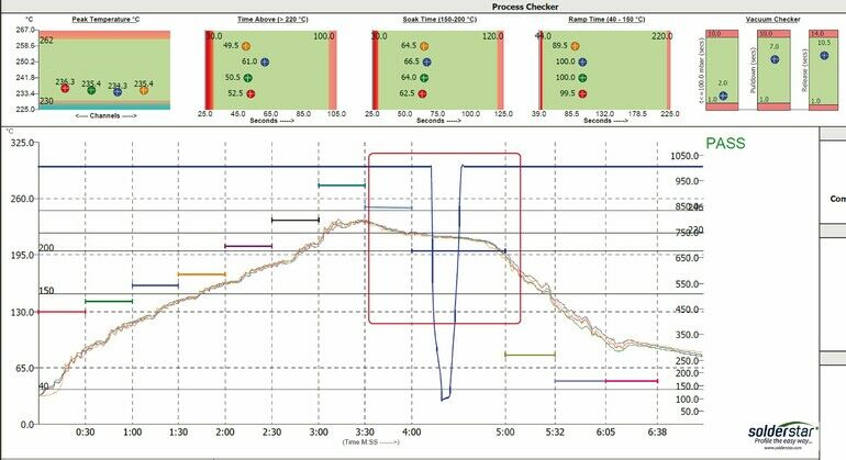
There are 8 heating zones, a vacuum zone, and 3 cooldown zones. Graphical representations at the top of the test report show 4 thermocouples and their corresponding paste targets. The vacuum sensor has an accuracy of ±1.5 mbar and operates in the range of 1200–10 mbar (900–7.5 Torr, ±1.125 Torr). The blue line on the chart represents the vacuum reading, and temperature plots. The process has passed thermocouple testing and has been used as a product for some time.
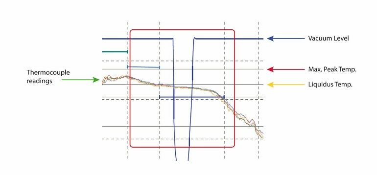
The image showing the close-up of the vaccuum stage highlights the need for monitoring the entire process instead of relying on dataloggers with only temperature measurement capabilities. It becomes evident that the PCB is cooling before entering the vacuum area, causing a semi-liquidus joint that will impair the expected out gassing from the joint. To address this, the PCB temperature profile should be adjusted to account for the cooling that takes place during the process.
With the increasing adoption of vacuum reflow, SMT managers are observing significant process improvements and void reduction, particularly in the high-end reliability sector. However, this technology also introduces new risks, specifically solder splashing and bridging during the vacuum phase. Some oven manufacturers address this concern by implementing staged controlled draw-down and release capabilities in their new ovens. While this solution reduces the issues, it adds another process parameter that needs to be confirmed.
Monitoring key parameters
Monitoring key parameters like vacuum pressure becomes critical to ensure the effectiveness of any changes made to the process. Engineers can create pass and fail rates based on their specific objectives by establishing defined tolerances. Utilising innovative software specifically developed for these measurements simplifies the monitoring process, facilitating user-defined targets tailored to individual quality requirements. To verify the vacuum profile for your PCB, use advanced profiling software to monitor three key factors:
- Pull-down time: the duration to reach the desired vacuum level.
- Hold time: the period under a specific vacuum level.
- Release: the speed at which the vacuum is released from the set point to ambient atmosphere.
Misplaced or moved components increase the risk of bridging, especially in vacuum reflow. Conducting root cause analysis is essential, considering factors like stencils, placement accuracy, paste viscosity, and the extra vibration caused by conveyor changes after population. In a vacuum reflow oven, a canopy drops over the PCB while transitioning from one conveyor to the vacuum zone conveyor, potentially introducing vibration at a critical profile stage. The transition conveyor introduced a new variable which could result in component shifts if not operating efficiently. The ability to monitor vibration on all three axes helps control this issue, sensitivities as low as 0.24mg are possible providing very detailed measurements and information.
Conveyor changes and the presence of fans or airspeed control in ovens impact the PCB profile. Understanding acceptable vibration tolerances varies depending on each build‘s specific PCB and components. Small caps and high-pitch components are more susceptible to shift and bridging under vacuum, while heavy PCBs with lower-pitch components are less affected. Common causes of problems in reflow ovens include fan speed before full surface tension and rapid conveyor speed changes.
Control the process
To fully leverage the benefits of modern reflow ovens in the electronics manufacturing industry, it is crucial to move away from limited traditional profiling equipment. Process engineers must understand and independently monitor the effects of the entire reflow environment to harness the unprecedented influence provided by controllable reflow systems. By integrating advanced parameter measurements and implementing comprehensive profiling techniques, the industry can significantly enhance efficiency, improve product quality, and effectively meet the ever-evolving demands of manufacturing.


