LED lighting dominates new designs for building and automotive applications. However, excessive operating temperature can change the chromaticity of the emitted light, reduce lifetime, and may destroy the LED. Proper thermal management must therefore restrict the temperature to below the safe maximum for a semiconductor device.
Applications
Among automotive lighting applications, matrix headlamps contain multiple emitters closely spaced on a single substrate to provide a high lumen output. Typically, a high-conductivity IMS featuring either an aluminium or copper baseplate is used. Non-reinforced dielectric, usually about 0.05mm-thick, minimizes CTE-related stresses between an aluminium baseplate and copper foil. In very high-power applications, a copper baseplate can avoid excessive stress due to CTE mismatch.
Spotlights or daytime running lamps (DRLs) often comprise multiple small boards, each containing two or three emitters. An IMS aluminium baseplate and 0.075–0.010 mm dielectric, resulting in thermal conductivity of 2–3 W/m.K is commonly used in these cases.
Turn signals are often subject to extreme constraints in size and shape because of their placement on a vehicle’s extremities. A three-emitter unit would need to dissipate about 7 watts, which can be achieved using an IMS with 0.05–0.075 mm dielectric thickness and thermal conductivity of about 3 W/m.K. Attaching the IMS to the vehicle chassis further enhances thermal dissipation.
General lighting and power
conversion
Applications such as street lighting require powerful, reliable illumination with extended replacement intervals. An IMS with thermal conductivity of about 3 W/m.K and a 0.075–0.10 mm dielectric effectively limits the LED temperature and preserves chromaticity, while allowing a high drive current.
In very high-power applications such as industrial welders, where the torch can draw 50 A to 400 A or more from chopper or inverter circuits, a heavy-duty copper foil, high-voltage dielectric, and a high-conductivity baseplate are combined with heatsinks and oil cooling.
High-power air-conditioners commonly use IMSs to connect power inverters and triac circuits to the air-cooled chassis or heatsink. An aluminium baseplate and conductivity of up to 10 W/m.K are typical.
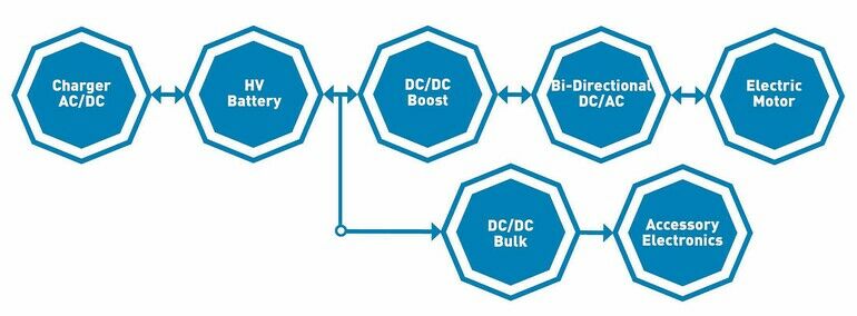
Automotive electrification
In addition to LED lighting, electric power steering (EPS) and electrical pumps and fans are replacing traditional mechanical or hydraulic units in today’s cars. Additionally, electric and hybrid vehicles contain AC/DC converters for regenerative braking and on-board chargin; DC/DC converters for dual-battery management and bi-directional power supply; high-voltage batteries, and traction motors. The power semiconductors in these systems can dissipate total power from several hundred watts up to tens of kilowatts.
Targets for module size and reliability can be met cost-effectively using a high-performing IMS with thermal conductivity of 3–4.2 W/m.K and 0.10–0.15 mm dielectric. Power transistors can be soldered to the IMS circuit layer as bare die. The baseplate is often integrated with a cast metal chassis or may be attached to a liquid-cooled heatsink.
Maximising IMS performance
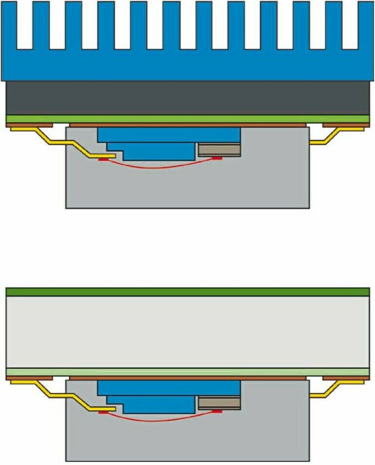
The application depicted above in the diagram shows a small automotive lighting assembly originally built using FR-4 board fitted with a heatsink. Exchanging this for IMS as seen in the lower image with a high-emissivity surface treatment helped achieve a thinner, heatsink-free assembly. The required thermal dissipation of 5 W was originally achieved using 20 mm x 20 mm FR-4 PCB with a 35mm heatsink; calculated using an online heatsink design tool.
Ventec has created a similar software application to calculate IMS parameters. This predicts that a 100 mm x 100 mm Ventec VT-4B5 IMS with standard brushed aluminium finish could dissipate 5 W without needing a heatsink (thus also eliminating the need for a thermal interface material). Recalculating with the added effect of a ER1 high-emissivity coating shows the IMS size can be reduced to 70 mm x 70 mm.
Potentially overlooked…
Although thermal conductivity, cost, and material thickness are the dominant selection criteria when choosing an IMS, there are several other factors to consider.
When choosing the dielectric, ensure that the breakdown voltage and thickness provide sufficient electrical insulation.
To decide the copper-foil weight, based on the application operating current, note that the IMS reduces I2R-induced temperature rise, thereby increasing the effective current-carrying capacity.
Consider creepage distance (also known as leakage distance) when designing for power applications. Creepage is dependent on the insulator’s comparative tracking index (CTI). Datasheets often give a CTI of 600 V for IMS materials, whereas the CTI for conventional FR4 is usually 175 V–249 V.
When choosing the base metal layer, consider the coefficient of thermal expansion (CTE) in addition to cost, rigidity, and weight – particularly in applications that experience intensive thermal cycling. Selecting a value that closely matches component and circuit-layer expansion can minimise solder joint fatigue. Large devices, extreme temperature differentials, and lead-free minimum solder thicknesses can all contribute to increased cyclic shear stress on solder joints.
Also consider the base material’s suitability for machining and post-forming operations.
Test methodologies
When characterising the thermal conductivity of their IMS products, manufacturers may choose from several standardised test methodologies. These include ASTM E1461 which is a contactless high-temperature test. Another is ISO 22007–2, performed using a 3mm-thick disc of the test material. ASTM D5470 also uses a disc-shaped sample of the test material and establishes a temperature gradient that can be measured in the steady state. In addition, there are various theoretical mathematical models such as the Bruggeman model.
All approaches have intrinsic inaccuracies, and all typically give different answers with the same material under the same conditions. Moreover, manufacturers’ datasheets do not always state the method used, which can prevent designers from making accurate comparisons. Independent testing is therefore recommended to predict performance accurately in the intended application.
Conclusion
IMSs can provide accurately controlled thermal management in systems that dissipate significant quantities of self-generated heat. There are many parameters that can be optimised, allowing for an effective, compact, and reliable solution.
Productronica, Booth B3.242


