The design concept of convection soldering equipment makes it relatively simple to scale the system to prevailing manufacturing conditions. Various system lengths with greatly differing conveyor systems can be implemented without having to change the physical heat transfer concept. Systems with one to four lanes are possible with or without center support. The modular design of the heating and cooling modules, which are always of the same size, makes it easy to vary system length and at the same time assures calculable heat transfer.
Nitrogen or air
Nitrogen or air is normally used as the heat transfer medium in convection systems. Due to the fact that the thermal conductivity of air is only marginally greater than that of nitrogen, but because air is more viscous, the heat transfer properties of both gases are comparable. Where reflow soldering is involved, this results in the advantage that the reflow soldering profile only has to be adapted minimally, or not at all, when changing back and forth between operation with air and nitrogen.
During nitrogen operation, a given volume of gas is fed to the system (approx. 20 cubic meters per hour) which is heated in addition to the circulating flow of gas. Average power consumption of the reflow soldering system is increased in this case by roughly 0.7 kWh.
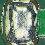
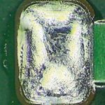
The nitrogen displaces the air, thus driving the oxygen out of the process chamber and creating a stable, inert process environment which prevents in situ oxidation of all materials involved in the soldering process. Wetting and solder spreading are improved, as revealed by a comparison of the molten paste deposits.
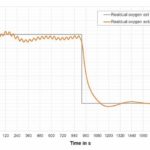
The reflow soldering systems from Rehm Thermal Systems make it possible to select the desired residual oxygen value. The user is thus provided with an additional parameter, making it possible to optimize soldering results for specific PCBs. There might not seem to be any apparent reason to increase the oxygen concentration in the process chamber, because oxidation impairs wetting performance.
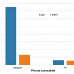
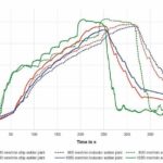
However, certain reflow defects, in particular tombstoning, can be influenced by wetting dynamics. Oxidation is prevented due to the lack of oxygen and wetting is accelerated. This results in a time offset where wetting of the two sides of a component is concerned – a tombstone occurs. And thus, higher concentrations of residual oxygen (e.g. 500 or 800 ppm) during reflow soldering can sometimes reduce the number of tombstones. Schake1) demonstrated how the residual oxygen level influences the tombstone rate for 0201 and 01005 components.
Temperature profiling
The purpose of temperature profiling is to generate a reliable, cohesive connection at all solder joints on the one hand, and to avoid exceeding the limits of the components heat resistance on the other hand. Heating system conveyor speed and blower frequencies can be adjusted in order to generate a suitable temperature-time curve.
Blower frequency
As already indicated by the name of the reflow soldering process, the process atmosphere itself becomes the heat transfer medium through the use of forced convection. Rehm uses innovative EC blower motors to induce convection flow, which can be directly controlled with the help of an integrated frequency converter.
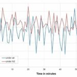
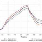
Being able to control volumetric flow provides the user with an additional option for influencing the temperature-time profile of their PCB. A comparison of two reflow soldering profiles were recorded using a VXP+734 with blowers, which were operated at different frequency settings. Other parameters, such as conveyor speed and reflow system temperature settings, were not changed. It is apparent how maximum solder joint temperatures change when lower frequencies are used: chip component from 241 to 230 °C, inductor component from 232 to 217 °C.
Blower frequency adjustment is rarely taken into consideration in actual reflow soldering practice, but it represents an entirely viable option for tricky tasks. For example, it’s used with Endress+Hauser’s patented back side reflow technology (patent DE 102 11 647 B4). With the help of this technology, THDs which are critical due to their heat resistance are soldered upside down in the reflow process. Heat input for the package, which is suspended underneath the PCB, is less during the soldering process than for the leads which protrude up through the PCB and are soldered at the top.
A DIP package is heated up to a desired reflow soldering temperature of 230 °C or higher, whereas the package suspended underneath the PCB remains significantly below the maximum permissible temperature of 200 °C. This was achieved, amongst other factors, through the use of different blower frequencies at the reflow system’s top and bottom heater modules.
Conveyor speed
PCB soldering results can be influenced by controlling the gaseous heat transfer medium (nitrogen or air) or blower frequency. Beyond this, the ability to change conveyor speed provides reflow soldering systems with an additional, effective method of altering the temperature-time profile. Even when heat zone temperature settings and blower frequencies remain constant, reflow soldering profiles can fluctuate due to a change in conveyor speed.
As speed is reduced; maximum temperature increases at all measuring points and differences in temperature between the various thermal masses on the PCB become smaller. The temperature of the atmosphere in proximity to the PCB is changed only marginally. In contrast, conveyor speed greatly influences heat transfer to the PCB.
As a result, it’s clearly advisable to adjust conveyor speed first and foremost– before changing any other system parameters – when optimizing the reflow soldering profile. It must be kept in mind that conveyor speed also has an effect on soldering defects, such as solder balls and tombstones. Trodler4) was able to demonstrate that the use of slow conveyor speeds and accordingly longer preheating times resulted in less beading on the PCBs. Wohlrabe5) was able to reduce the number of tombstones with lower speeds.
CoolFlow method
Whereas the options described above for inerting the soldering process and influencing temperature-time curves have long been known as separate parameters, multiple, simultaneous use of liquid nitrogen as a coolant and as an inert process medium is an innovation.
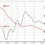
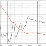
With its CoolFlow method, the company has implemented a concept developed by Air Liquide GmbH (EP 2 771 145 B1), for the first time ever with relevance for machine technology, which entirely banishes previously common coolant water from the reflow soldering system. Cooling is accomplished in these systems by means of liquid nitrogen, which is then used to render the process chamber inert after phase transformation to the gaseous state. By waiving coolant, water provides the operating company with a power consumption advantage. With the CoolFlow option, the VXP+ soldering systems consume 10 kWh or less in the operating state under actual production conditions. At the same time, very steep cooling gradients can also be set up with the CoolFlow, for example in order to shorten cooling time. Cooling gradients of up to –6 K/s are possible with the Rehm CoolFlow option.
Within the framework of their examinations, Villain3) and Grözinger2) have adequately answered the question as to how a steep cooling gradient affects the reliability of the solder joints. With the help of dendrite arm spacing measurements conducted by means of EBSD for 0402 components on NiAu and iSn PCB finishes, Villain verified only a slight tendency towards grain refinement of the solder joints due to rapid cooling. In consideration of the scatter range, the cooling gradient and the finish of the PCB have no significant effect on the microstructure of the solder joints.
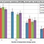
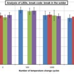
The following shear force measurements conducted by Grözinger after the alternating temperature test (- 40/ + 125 °C) confirm the findings obtained by means of metallurgical examinations and verify that a cooling gradient within the generally accepted reflow soldering range of up to –6 K/s has no significant influence on the reliability of the solder joints. The reduction in shear force after 250, 500 and 1000 cycles lies within exactly the same range for various cooling gradients for the examined CR1206 and LED components. Consequently, the CoolFlow method opens up a considerably larger process window for the user, in particular when soldering very heavy PCBs.
Conclusions
This article has answered several essential questions concerning the configuration of convection soldering systems and the resulting effects on the soldering process. The company’s reflow soldering systems offer a great variety of system parameters, which make it possible to meet the most diverse soldering requirements. The combination of tried and true system options with newly developed measures, such as EC motor technology or CoolFlow, not only permits improved process technology, it also provides a solid foundation for laying out sustainable, Industry 4.0 compliant production machines.
productronica, Booth A4-335
Sources
- Jeff Schake, Mass Reflow Assembly of 01005 Components, Proceedings Apex 2007.
- T. Grözinger, Hahn-Schickard Institut Stuttgart, Bericht CoolFlow, Air Liquide Deutschland, 15.07.2016.
- J. Villain, HS Augsburg, Die Verbindungsqualität von Lötstellen Einfluss der Abkühlgradienten, Multipler Nutzen des Stickstoffs in der Elektronikfertigung, Rehm 18.2.2015.
- J. Trodler, W. Schmidt, Bleifreie Lötprozesstechnik: Haupteinflüsse und Wechselwirkungen auf die Lötqualität beim Verarbeiten von SAC-Lotpasten, Proceedings 3. DVS/GMM-Fachtagung 2006.
- H. Wohlrabe, T. Herzog, S. Schröder, Bericht zur Untersuchung des Einflusses von verschiedenen Löt- und Materialbedingungen auf die Qualität von gefertigten SMD-Baugruppen – Versuch 2, 2007.
Zusammenfassung
Reflow-Lötanlagen sind ein wesentlicher Bestandteil jeder SMT-Fertigungslinie. Dieser Artikel beantwortet einige wesentliche Fragen zur Konfiguration dieser Systeme und den daraus resultierenden Auswirkungen auf den Lötprozess.
Résumé
Les systèmes de brasage par refusion sont une partie essentielle de toute ligne de production SMT. Cet article répond à quelques questions essentielles sur la configuration de ces systèmes et les effets qu‘il induisent sur le processus de brasage.
Резюме
Системы пайки оплавлением являются неотъемлемой частью каждой производственной линии поверхностного монтажа. В этой статье даются ответы на некоторые важные вопросы, связанные с конфигурированием этих систем и их влиянием на процесс пайки.
