AOI systems are an essential element in the PCB production process in order to guarantee a reliable quality assurance. The user can choose from a variety of system options which are characterised by diverse performance parameters so that a broad spectrum of quality demands can be satisfied. For optimal fault detection with independence of the PCB layout and the assembly parameters a high-end angled-view inspection is indispensable.
Jens Kokott, Manager AOI/AXI systems, Goepel electronic
The application of AOI systems is necessary for the inspection of the solder joints at PLCC components and furthermore, offers a higher inspection quality for pins of all kinds of IC components (e.g. SO, QFP, etc.). Regarding the last-mentioned solder joint type an orthogonal inspection is possible, however the layout at the solder joint has a crucial influence on the reliability of detection.
In this matter especially EMS providers face the difficulty not to be able to control the design of the pads and arrangement of components; hence the consideration of layout guidelines will stay an illusion. To put things right an angled-view can provide image information for additional analyses. However, this additional viewing direction should not be considered a remedy for increasing the quality of detection, because its application brings with it several boundary conditions which also influence the overall process of the Automated Optical Inspection. Besides an increased expenditure of time due to additional image capturing and the considerably smaller field of view, the arrangement of the components on the PCB can constrict the view on the inspected solder joint also with an angled-view inspection. Taking into account all these particularities Göpel electronic developed the rotating angled-view module „Chameleon“ which allows, together with an intelligent verify function, a layout independent and reliable fault detection. In the following paragraphs the application of this innovative new development is explained, especially in regard to the detection of Lifted Leads in various layout and assembly situations.
Detecting critical faults – under all circumstances?
Lifted Leads belong to the most critical faults in the production of PCBs. They result e.g. from lifted pins or from insufficient wetting (e.g. through oxidation of a pin). In the electrical test (ICT, Boundary Scan, functional test) they may perfectly show an electrical contact to the pad on the PCB – however, in the actual use there can be discontinuities and hence a malfunction of the PCB.
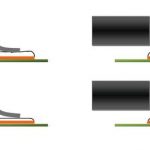
The detection of Lifted Leads is complex due to their diversified appearance. The following parameters have a significant influence on the quality of the solder joint/Lifted Lead:
- the solder quantity
- the width of the pad
- the length of the pad
- the solder flow at the pin foot
- flow behavior on the pad
- the height of the pin.
All these criteria are combined in reality so that there is a variety of possible appearances. In the daily use there may be Lifted Leads that are detectable with orthogonal inspection, however, this is significantly dependent on the PCB layout and the applied solder quantity.
An angled view alone is not enough…
As already mentioned, the angled-view is considered as THE remedy for maximum fault detection. However, a critical approach to the AOI systems is absolutely necessary as a range of parameters have different impacts on the performance:
- The field of view (FOV) of the angled view is responsible for the inspection speed of the complete system. As a comprehensive use of the angled view is necessary for the inspection of complex PCBs with a high number of ICs, the FOV is decisive for the time of inspection.
- The depth of focus and the image quality of the angled view is also decisive for the whole FOV on the PCB as well as in regard to the height extension of the components. Consequently, it influences the inspection quality and speed.
- The sole evaluation of the front menisci at pin solder joints has only a limited informative value regarding the solder quality. An angled inspection of the IC pins enables an optical inspection that resembles an IPC-conform test much more.
- Especially for the inspection of fine pitch ICs up to 0.3mm a sufficient resolution is necessary for safe fault detection.
- If there are higher components in front of the tested pins there might be overlaps in the angled field of view. One tries to evade this situation with design regulations, however, this is a question of practicability.
- A deflexion of the PCB during the inspection process might cause a displacement of the inspection positions in the camera image of the angled-view. To counteract this effect adequate compensation algorithm can help.
- Components in an angled position other than the 90°-steps cause extremely higher efforts regarding the programming time, because the test samples that are defined in the library (test units, macros etc.) can ot be used and a manual adaptation is necessary.
- Besides the image capturing using angled view, an intelligent verify function is necessary in order to reach a safe fault detection with minimum false call rate under the above named circumstances.
Coming from theory to practice and innovative results
As a basis for the development of a powerful angled-view module, the company has developed a catalogue that contains all appearances of Lifted Leads and their combinations. Based on this catalogue, all classes of appearances were backed up by real samples in close cooperation with customers. The result is a pool of thousands of Lifted Leads in different appearances. Based on this, a method of image capturing was identified by modifying the directions of viewing and illumination, which ensures the detection of all catalogued Lifted Lead variants. According to the requirements of the image capturing, an angled view module was developed that is distinguished by an extraordinarily big field of view (42mm x 42mm) with superior image quality and depth of focus, as well as a resolution of up to 10.5μm/pixel.
On the basis of the images captured in this way, an algorithm was developed that enables the automatic detection of Lifted Leads under all circumstances.
The solder joint inspection close to IPC was paid special attention to. That is only possible due to an angled-view inspection f the IC pins. This approach, using an intelligent optical design, allows the simultaneous inspection of two opposite pin rows of an IC. Hence, there is a significant advantage in the inspection time as e.g. for an SO-IC image capturing from only one direction is necessary. Even for components with four pin rows, there are only two inspections necessary with one 90° rotation of the viewing direction.
The final verification of the algorithm with all available real Lifted Lead samples incl. the application in production resulted in a 100% fault detection without increase of the false call rate. The application in critical assembly situation was also considered in the development of the angled-view module (e.g. covering by higher components) along with the inspection of components in any angular position. Due to these considerations, the rotatability in 1° steps over an area of 360° was integrated in the module.
The benefit for the user is demonstrated in the following points:
- 1. For components in different angular positions (e.g. 20°) no adjustment of the inspection position or the parameters is necessary as the viewing direction has only to be adjusted to the respective angular position (e.g. 20°), and the inspection can be carried out using a standard library sample in 0° position.
- 2. If the viewing direction is obstructed by components, it is possible to turn the viewing direction for a few degrees until the solder joints are completely visible. Consequently, a safe fault detection is guaranteed.
Summary
For assuring highest quality demands in the production of PCBs a powerful angled-view inspection guarantees layout independent and safe fault detection. The size of the captured field of view influences the inspection speed of the AOI system significantly. The free rotation of the viewing direction in an area of 360° allows an easy inspection of solder joints that might be covered by components in front of them.
A modular integration into in-line and stand-alone AOI systems allows the module to be used for a significant quality increase even for smallest batches.
SMT/Hybrid/Packaging Booth 6-410 & 7-404
ZUSAMMENFASSUNG
AOI-Systeme sind anerkanntermaßen ein wichtiges Element in der Elektronikfertigung zur Sicherstellung einer hohen Qualität. Das Schrägblickmodul Chameleon garantiert nun eine maximale Fehlererkennung unabhängig von Leiterplattenlayout und Bestücksituation durch eine leistungsfähige 360°-Schrägblickinspektion.
Les systèmes AOI d’une manière générale
sont un élément essentiel de la production électronique en termes d’assurance de la qualité. Le module d’inspection rotatif Chameleon garantit désormais une détection maximale des erreurs quel que soit le dessin du circuit imprimé et son équipement, le tout grâce à une inspection optique rotative sur 360 °.
Share:
