
Previously found only in the lab, cleanliness testers are migrating to the production line as manufacturers realise their potential as a process control tool for lead-free assembly. This article explains what’s behind the move.
During the 70’s, the dramatic increase in the electronics used in modern weapons was accompanied by a demand for increased reliability. US and British military planners realised, for example, that a submarine carrying a nation’s nuclear deterrent is hardly doing its job if it’s holed up in port for yet another round of repairs to the electronics. One major threat to military electronics, then as now, is the growth of dendrites and intermetallics that ultimately cause short circuits. In a humid environment and the presence of an electrical basis, excessive ionic contaminants on an assembly can cause problems such as shorting between board traces due to electrolytic dendrite growth, erosion of conductors, or loss of insulation resistance (see figure 1). The solution is to eliminate the ionic contaminants (as minimising the humidity or electrical bias in an operating environment is virtually impossible). In practice, it’s impossible to completely remove all contaminants, so back then, the military authorities put a “stake-in-the-ground” to provide their contractors with a “Go/No-Go” threshold of acceptable ionic contaminants that might remain on the circuit. This requirement has never changed – although the original threshold has subsequently been lowered to today’s 1.5 μg/cm2 NaCl equivalence (see IPC-J-STD001D Section 8.3.6.2). Note that with modern densely packed assemblies, this level is almost certainly far too high. Consequently, a figure of around 0.2 μg/cm2 is commonly used.
The military standard was seized upon by many high reliability electronics manufacturers looking for a method to underwrite the integrity of their products. However, measuring contamination was a challenge. What these manufacturers cried out for was a simple, automated tester to perform the measurement. The military provided the answer in the form of the equipment that had been developed as a useful Process Control tool and used for the original experiments. All it took was an enterprising individual to commercialise the machine, such as industry guru Brian Ellis of Protonique, and the practical “Contaminometer” was born.
The Contaminometer has since lived a quiet life, hidden away in the lab at high reliability manufacturers diligently testing occasional samples to ensure contamination is below the threshold. But all that has changed with the advent of lead-free soldering. Lead-free soldering brings with it a dramatically narrowed process control window. Whereas previously, tin lead soldering offered a wide tolerance of the processing parameters, lead-free is much less forgiving and manufacturing engineers are searching for tools to help them maintain process equilibrium. One answer is the Contaminometer.
Sources of ionic contamination
Before the advent of “no-clean” electronics assembly – introduced as a result of the Montreal protocol, a globally supported initiative to eliminate CFCs – fluxes contained rosin (the sap from pine trees) and alcohol to keep the rosin in a liquid state. The proportion of rosin used in these old fluxes was anything between 15 and 50 percent.
Flux was needed for two reasons:
- To remove surface oxides from PCBs and components to promote correct alloy formation
- To act as a heat transfer medium to ensure correct soldering temperatures
Once its job was done, the flux residues were removed from the PCB by aggressive solvents. However, the Montreal protocol put paid to that process. The solution was to implement a no-clean process whereby it was “safe” to leave residues on the assembly. But these safe levels couldn’t be met by the traditional high solids fluxes – they were just too aggressive and dirty. Flux manufacturers developed “low solids” version of their popular fluxes that, while demanding enhancements in process control, were designed to be left on the board forever.
However, flux is not the only source of contamination in the electronics assembly process. Common sources of ionic contamination include etching, plating, tinning or levelling residues, poor solder masks, undercured permanent or temporary solder masks, dust, moisture, oil pollution from finger prints, component packaging materials, and machine maintenance oils (especially from wavesoldering conveyors).
For high reliability product suppliers – such as those supplying the aerospace sector – a no-clean regime introduced a daunting challenge. While the manufacturers didn’t want to clean their assemblies, they couldn’t risk the levels of contamination post-assembly exceeding the prescribed threshold. Failure of high reliability products could mean loss of life. Manufacturers solved the challenge by periodically testing samples with a Contaminometer to ensure they were “clean”.
For manufacturers of products destined for normal use – such as calculators, smoke detectors and electronic toys – a Contaminometer wasn’t a requirement as an occasional failure simply meant a warranty return rather than a lawsuit from a deceased user’s estate. But the status quo for all manufacturers has changed with the replacement of tin/lead solder brought on by the need to meet Europe’s restriction of hazardous substances (RoHS) regulations. These regulations – introduced in July 2006 and likely to be followed by similar legislation in other regions – ban the use of lead (among other defined substances) in the manufacture of electronics; completely changing the electronics manufacturing landscape.
Soldering without lead
The International Electrotechnical Commission (IEC) and US-based Association Connecting Electronics Industries (IPC) – respected institutions in the electronics manufacturing sector – recommend high tin alloys as the best replacements for tin/lead solder. Specifically, the IEC states: “The preferred alloy composition should be either Sn96.5Ag3.0Cu0.5 or Sn99.3Cu0.7. An alloy consisting of 3 to 4 % Ag and 0.5 to 1 % Cu with the remainder made up of Sn may also be used instead of Sn96.5Ag3.0Cu0.5. A solder alloy comprising 0.45 to 0.9 % Cu with the remainder made up of Sn may be used instead of Sn99.3Cu0.7.”
The most popular choice among manufacturers moving to lead-free soldering is Sn96.5Ag3.0Cu0.5. This ternary alloy melts at a temperature of 219 °C – far higher than the 183 °C of eutectic tin/lead. The implications of this higher melting point are many, but in essence, the effect is to considerably tighten the process window. Manufacturing engineers supervising a lead-free process now need all the help they can get with process monitoring. The Contaminometer is one tool that can help, both at the beginning of the process and after wave solder.
Because there is much less tolerance in the soldering process, dirty boards – that could have once been soldered by using a more aggressive flux – now can’t be tolerated. Measuring the cleanliness of the bare boards with a Contaminometer ensures that those entering the process have the best chance of soldering without problems. (The test also provides good feedback of how well the storage process is working.)
At the end of the process the contaminator really comes into its own. The results will quickly identify trends in the manufacturing process that can be altered before they become a problem. For example, if flux composition starts to stray from the optimum, the residues on the board will begin to change. The sensitivity of the Contaminometer is such that this change will be detected well before soldering is effected.
Moreover, a Contaminometer is an excellent guide to the effectiveness of the preheat profile. Preheat is a critical factor in the success of lead-free soldering. It is a delicate balance between ensuring the flux does its job, and ensuring the board is at a sufficient temperature such that when it hits the – now much hotter – solder bath the thermal shock isn’t excessive. The temptation is to “wind-up” the thermostat: But this has a seriously detrimental effect on the FR4 substrate (a material that was designed to work well with tin/lead processing, not the elevated temperatures of lead-free alloys).
If the preheat temperature is too high it has a dual effect: The flux vitrifies, preventing it doing its job and coating the board with unacceptable contamination. Secondly the board expands dramatically “encouraging” absorption into the laminate; the consequent risk of phenomena such as delamination becomes higher, as do subsurface reactions of residual contamination from the chemicals used in the assembly process that can cause later electrochemical reactions and reliability problems. A Contaminometer will rapidly pick up on these “overheating” effects before they affect the quality of the soldered products.
Contaminometers are exceptionally useful measurement instruments for Statistical Process Control (SPC) of the soldering process (and cleaning if manufacturer is still using a cleaning operation). By testing a predetermined number of samples per hour or per day, fluctuations in the level ionic contamination on the assemblies will be detected, rapidly alerting the operator to a process variation. Consequently, an engineer can tune the process before the contamination level exceeds the 1.5 μg/cm2 (or lower) NaCl equivalence threshold and compromises the quality of the product. Better yet, especially in an age where most companies are ISO 9001 accredited, a hard copy will document the test results in an easy-to-read graphical representation.
Simplicity of operation
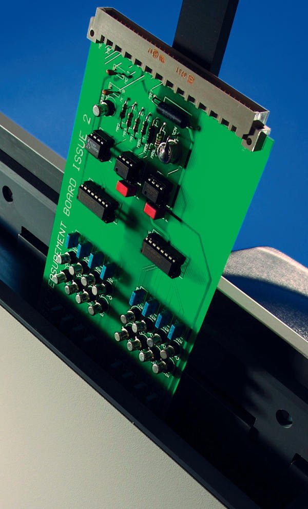
While the science behind Contaminometers is complex (see sidebar “Testing, testing”), operation needn’t be. This is especially important if the equipment is going to be used as a process monitoring tool where the machine is likely to be operated by unskilled personnel. Fortunately, modern machines have been designed so that the only manual task is to insert the PCB at the beginning of the test and to remove it at the end (see figure 2). All other test cycle operations are automated. A typical test procedure starts as with tank filling and solution preparation. The solution is prepared for a new test by pumping through a mixed-bed ion exchange column until it reaches an extremely low level of conductivity (or is “re-generated”). The solution is then homogenised. The test then follows the sequence listed below:
- Insert test piece. This causes a volume of test solution to overflow into a calibrated overflow tank for measurement (corrected to compensate for components if necessary).
- As the solution is pumped across the test piece via the measuring cell the rise in conductivity is monitored. The test ends either when a pre-set time limit (between 3 and 15 minutes) is reached or when the conductivity level rises less than 1 percent of the absolute value over a period of 48 seconds.
- On completion of the test, the results are processed and analysed by the computer and may be viewed on-screen. The results are stored on the hard disk for future use and for comparison purposes.
- The overflow chamber empties and the tank is replenished and regenerated for further tests.
From lab to shop floor
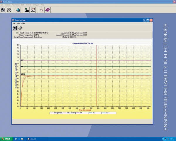
The manufacturing regime imposed by the change to lead-free demanded much tighter process control. Whereas previously an engineer could “tune” the process by increasing flux activity, changing conveyor speed or increasing preheat on virtually an ad hoc basis, soldering with high tin, high melting point alloys is a different matter. Even a slight change from the optimum can result in a flurry of failures at the ATE station – or worse, later when the product is in the field and the rework costs have escalated a hundredfold. There are several tools available for SPC but perhaps the most overlooked is the Contaminometer. This is a highly accurate tester useable by unskilled staff yet able to quickly measure the level of contamination on bare boards and assemblies. The information is presented in a graphical format and can be used as data for further statistical analysis (see figure 4). The degree of contamination directly correlates to the likelihood of a bare board successfully soldering, or whether an assembly has been soldered at less-than-optimum process parameters. Moreover, the results of the test can also indicate whether the assembly is likely to suffer a field failure as a result of exposure to conditions likely to promote the growth of intermetallics. In an age where adherence to legislation, stringent process control, high throughput of quality products and low consumer tolerance of failures are conflicting pressures on manufacturing engineers, the Contaminometer is one reliable tool that can make the job easier.
EPP Europe 450
Contaminometers
Gen3 Systems manufactures both static and dynamic Contaminometers. These precision instruments (the CM Series) were originally developed by Protonique, a company started by industry guru Brian Ellis. Identical machines also featured in the early development programmes of “cleanliness measurement” carried out by the US Department of Defense at China Lake in the 1970s. These programs determined the effects of contamination on high reliability assemblies and set the threshold for the maximum amount of μg/cm2 NaCl equivalence acceptable on a “clean” electronic assembly.
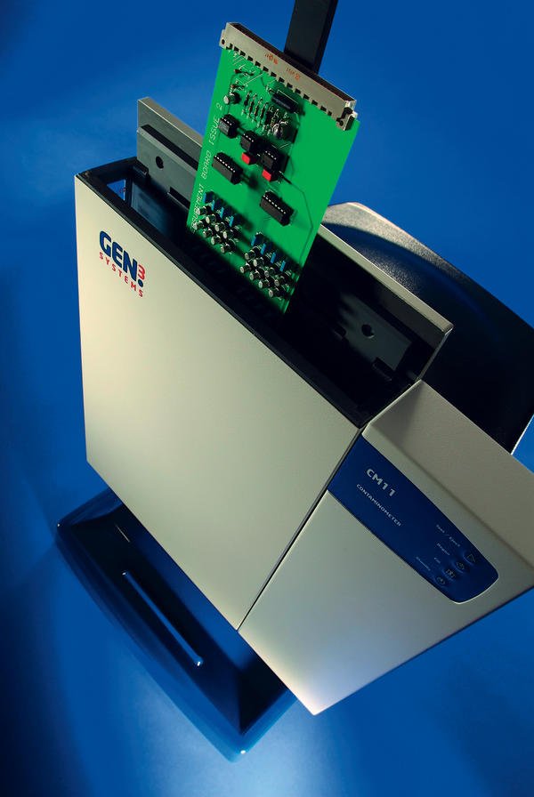
The CM Series comprises the CM11 (see figure 5) and CM12 table top models for small size PCBs and components and the CM60 floor standing model, designed to test large PCB panels and assemblies. The CM60 can be equipped with one of two different sized tanks dependant upon the size of the test pieces. The CM90 is a Static Tester that is available since end of 2007. The CM60 employs a “Volumetric Measurement Cell” (VMC) that, by measuring the amount of test solution displaced by the item under test as it is immersed into the test chamber, determines more accurately the amount of contamination dissolved. All components fitted to the CM Series Contaminometers have been carefully chosen to ensure reliability. The hydraulics of each instrument are thoroughly tested and a special grade polymer is used for tanks and piping in contact with the CM Test Solution. This solution is a mixture of reagent grade 2-propanol and ultra-pure de-ionised water mixed at either 50 or 75 percent as required by the applicable standard.
The user-friendly software running under Windows XP or Vista gives on-screen instructions to guide the operator through the test cycle. The software can display up to 20 test results in a two-dimensional or three-dimensional representation, rotatable for ease of analysis. The software is further designed to enable easy export of test results into other word processing and SPC software packages.
zusammenfassung
Der bleifreie Lötprozess wird durch ein enges Prozessfenster bestimmt. Wo es früher beim Löten mit Blei noch eine große Toleranz bezüglich der Prozessparameter gab, verzeiht der bleifreie Lötprozess nur wenig. Ingenieure in der Produktion suchen daher nach Tools, die ihnen helfen, das Prozessgleichgewicht stabil zu halten. Hier kann ein Contaminometer helfen. Diese Tester halten inzwischen in der Produktion Einzug als Instrumente zur Prozessüberwachung.
Le brasage sans plomb est déterminé par une fenêtre de process étroite, contrairement au brasage au plomb qui offrait une large tolérance en matière de paramètres de process. C’est pourquoi les ingénieurs de production sont à la recherche d’outils contribuant à maintenir l’équilibre des process. Dans ce cadres, un contaminomètre peut s’avérer utile. Ces testeurs ont désormais pris place dans les ateliers de production en tant qu’instruments de surveillance des process.
Il processo di saldatura senza piompo prevede parametri di processo molto rigidi. Mentre con la saldatura con piombo si aveva una grande tolleranza dei parametri di processo, questo non avviene con i processi senza piombo. Gli ingegneri della produzione ricercano quindi strumenti che contribuiscano a mantenere l’equilibrio del processo. Può essere d’aiuto un contaminometro. Questi tester sono strumenti per il controllo del processo produttivo.
Testing, testing
The Contaminometer uses a mix of alcohol (IPA or Propan-2-Ol) and ultra-pure de-ionised water to dissolve flux residues and ionic salts. The dissolved ionic substances alter the conductivity of the test solution; the test equipment precisely measures the change and expresses it as µg/cm NaCl equivalence. Other common names for the machines are ROSE (Resistivity of Solvent Extracted) or SEC (Solvent Extract Conductivity) testers. The measurements are made in accordance with IPC/ANSI-J-STD001D and UK DEF-STD and other international specifications.
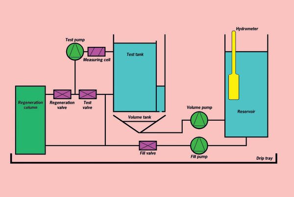
A contamination test system uses either a static or dynamic test method. Static testing uses a pre-computed volume of solution to carry out the test. Dynamic testing recirculates the total volume of solution to a given surface test area. Contaminometers are sophisticated instruments incorporating several features to improve the precision and repeatability of the cleanliness measurement. For example, in operation the tester automatically repurifies the solution each time a new test is run using an easily changed regeneration or de-ionising cartridge (see figure 3).
Some machines utilise a solid gold measuring cell, ballistic amplifier and a vigorous pumping system to achieve measurement accuracy of less than 0.005 mS/cm even at very low conductivity values. Machine design avoids polarisation effects between electrodes that might otherwise occur when using DC test currents. And error signals caused by both DC and AC currents are eliminated.
A thermistor is positioned in the test cell to measure temperature for feedback to the automatic temperature compensation; all measurements are related to the international standard of 20 °C (68 °F). Testers use a complex algorithm to compensate for ambient temperature, circuit volume and atmospheric absorption of iogenic gases. The analysis of the contamination test data uses a complex curve-fitting routine to give an indication of the ionic contamination on the circuit. The unit then provides a graphical display of test results featuring auto-ranging of curves in units of μg/cm2 NaCl equivalence. Contamination is plotted against time and the curve is automatically extrapolated, producing meaningful data even for a short test. Graphical review of test data includes a pass/fail analysis. The Contaminometer software includes statistical evaluation of up to fifty test results, but the data can also be imported into other software packages for further enhancement or appraisal as required. It’s advisable to ensure the test data meets the requirements of international and military specifications as documented in MIL-P-28809 (which, incidentally, is obsolete, but still referenced by the industry), DEF standard 00–10/3, IPC-J-STD 001D & IPC-TM-650 and IEC specifications.
Share:


