Conti Temic Microelectronic GmbH in Nuremberg specialises in the manufacture of highly complex electronic assemblies for the automobile industry. Soldered joints with a low number of pores, which cannot be produced using conventional reflow technology, are required for the manufacture of new hybrid assemblies for the automobile sector.
Christian Ulzhöfer, SMT Wertheim (Germany)
SMT Maschinen- und Vertriebs GmbH in Wertheim has developed a vacuum reflow soldering system which combines conventional reflow soldering with a vacuum process in order to meet the stringent demand for soldered joints with a low number of pores.
The modular design of the in-line vacuum reflow system enables heating zones with variable length, different vacuum chambers, various conveyor systems (single, dual or triple-track conveyors) and different cooling zones to be combined. The system can therefore be set up individually for the required throughput and product group.
Soldering can be carried out in the system with and without vacuum and with N2 inert gas atmosphere or with air. The user therefore has at his disposal a system which combines all the requirements of the reflow process in a single unit. The vacuum soldering process and the percentage of pores in the soldered joint are discussed below using the assemblies produced by Conti Temic in Nuremberg as an example.
Soldered joint and pores
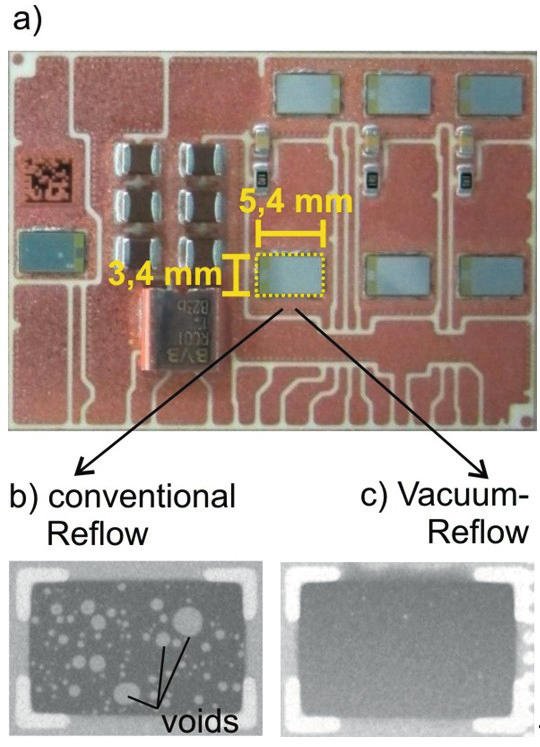
The assembly produced by Conti Temic is a substrate based on DCB (direct copper bonding)
Technology on which bare dies (integrated electronic components without housings) are soldered using a lead-free reflow process. The bare dies have an area of 5.4mm × 3.4mm and a height of 0.3mm.
Pores are gaseous inclusions in the soldered joint which lead to a reduced thermal conductivity between the printed-circuit board (PCB) and the device component.1,2 When components carry high electrical currents, as is the case with the bare dies investigated here, the resulting heat can no longer be adequately dissipated via the porous soldered joint. This can result in high component temperatures and ultimately to reduced performance or component life.3 The percentage of pores in the soldered joint can be reduced and the thermal conductivity improved by using vacuum soldering processes. The X-ray images of the bare die soldered joint produced using a conventional soldering process and using the vacuum soldering process presented here. A qualitative comparison of these images clearly shows that with the conventional reflow process many pores are present in the soldered joint over a large proportion of the area, while the number of pores is reduced to virtually zero by using the vacuum process.
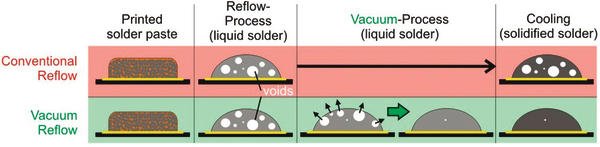
The difference between the conventional and vacuum reflow solder paste fusing process is shown clearly. The solder paste is fused in hot air or in a hot N2 atmosphere by means of the reflow process. In doing so, gaseous inclusions are produced in the soldered joint and, in the conventional reflow process, are incorporated by the cooling and solidifying of the solder. In the vacuum reflow process used here, the solder is likewise heated and melted. This is followed by the vacuum step in which the pores expand and are removed from the surface of the joint into the vacuum. The percentage of pores in the soldered joint is reduced; the soldered joint is more solid and therefore has a higher thermal conductivity which in turn has a positive effect on the component performance and life.
The vacuum reflow process
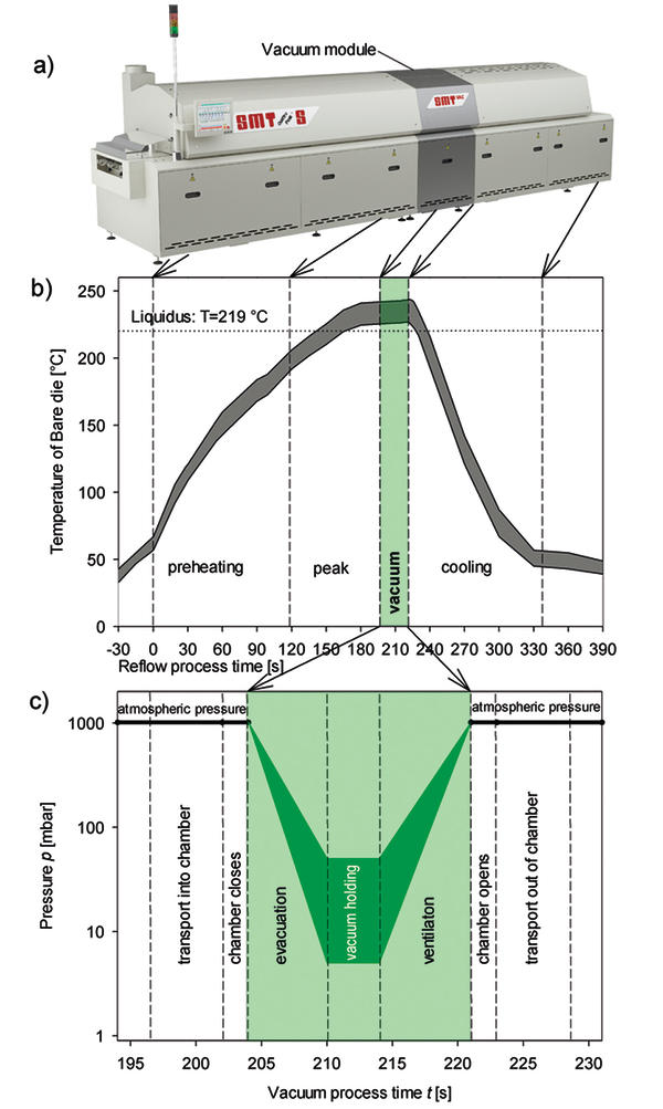
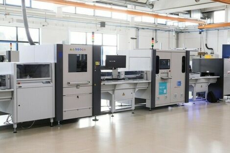
The vacuum soldering system developed by SMT Wertheim has two edges of the assembly lie on a chain (3mm or 5mm edge contact) which transports it through the machine from left to right. The left-hand part of the soldering system shown in white comprises the pre-heating zone and the peak zone in the top and bottom part of the heating chamber (Quattro-Peak). The vacuum module is on the right of the heating chamber. It has an additional peak zone to enable the overall temperature profile of the soldering process to be adjusted more flexibly. In this overall heating zone, the assembly is heated by convection using air or nitrogen until the solder melts.
The assembly with the liquid solder is transported out of the convection zone into the vacuum chamber in which the actual vacuum process takes place. After this vacuum process, the assembly is transported to the cooling zone where it is cooled to the required temperature using air or nitrogen.
The length of the heating zone and the cooling zone can be chosen individually and matched to the printed circuit board throughput. The type of vacuum chamber chosen here accommodates printed circuit board sizes up to 510mm x 320mm. Other types of chamber for printed circuit board sizes up to 600mm x 450mm are available.
The temperature profile of the bare dies measured by means of a temperature recorder as a function of the overall process time. At time t = 0 s the assembly is at the start of the first pre-heating zone. At t = 118 s the assembly has been transported to the peak zone. The melting temperature (liquidus) of the solder is 219 °C. The vacuum chamber is heated so that the assembly and the chamber have the same process temperatures. The heat radiation balance between chamber and assembly guarantees that the temperature of the assembly is constant even in vacuum, and the solder remains liquid. The assembly with the liquid solder is transported into the vacuum chamber and the chamber closes.
In the next process steps, the chamber is evacuated, the vacuum is maintained and the chamber is subsequently filled with air or nitrogen. The evacuation time, the final pressure, the vacuum retention time and the filling time can be set individually. Chamber pressures down to 5mbar are possible. The pores are effectively removed from the soldered joint.
After the vacuum process, the chamber opens and the assembly with the liquid solder moves into the cooling zone. Here, the solder is solidified by blowing cold air or nitrogen onto the assembly.
Statistical evaluation of the number of pores
The specification defined with the customer states that pores must cover less than 10% of the area of the soldered joint between the bare die and the DCB surface. The data presented were obtained from Conti Temic in Nuremberg and subsequently evaluated. In order to be able to assess the effectiveness of the vacuum reflow process compared with conventional reflow soldering, assemblies were soldered using the conventional and the vacuum process.
The conventional reflow process had a similar temperature profile to that of the vacuum process. The absence of the vacuum chamber in the conventional process was compensated for by a lower throughput speed. As a result, the assembly was in the peak zone for the same length of time and the time above the liquidus temperature was also the same. 119 soldered joints were x-rayed for the conventional reflow process, and 1806 soldered joints for the vacuum reflow process.
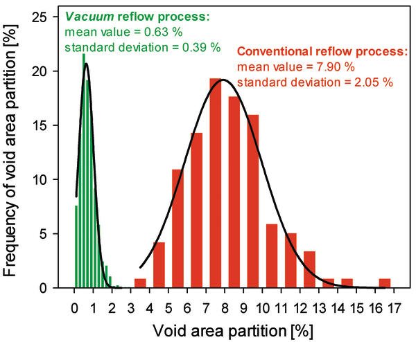
For the conventional reflow process, the average percentage of pores in the soldered joint is 7.9%. The „width“ of the normal distribution is defined by the so-called standard deviation s and in the conventional process is 2.1%. The process capability value (CpK value) resulting from this distribution and the desired target value of less than 10% pores in the soldered joint is only 0.3. This is a very much smaller and poorer value compared with a required CpK value of at least 1.7. A larger proportion of the conventionally treated soldered joints (red bar) has a pore frequency of greater than 10%. These joints and the corresponding assemblies would have to be rejected. As every assembly has 7 bare dies, the proportion of assemblies with a percentage of pores greater than or equal to 10% is seven times greater than for the soldered joints. The process capability of the conventional reflow process is therefore not achieved with the defined requirements.
As a result of the vacuum reflow process, the average percentage of pores in the soldered joint is reduced to a mean value of 0.63%. The standard deviation is still only 0.39%. This results in a larger CpK value of 8.0. The distance between the mean value and the upper tolerance limit of 10% pore content is 24 times the standard deviation. The quality number of 6 standard deviations (6 s) which is frequently aspired to is therefore clearly achieved, and the process capability is fully guaranteed. The high demands on the percentage of pores in the soldered joint can be fully guaranteed with the vacuum reflow process.
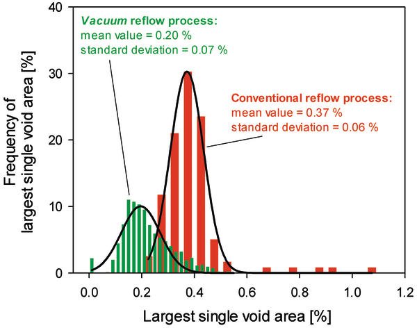
As well as the total surface percentage of all pores, the surface percentage of the largest pore is also important. The largest pore to a great extent determines the thermal conductivity in the appropriate region beneath the bare die. Here too, the smaller the largest pore, the better the thermal conductivity in the soldered joint. The same soldered joints as in the previous evaluation were investigated. In the conventional process, the mean value was 0.37% and the standard deviation 0.06%. The largest pores take up more than 1% of the soldered joint. The size of the remaining pores is reduced by the vacuum process. The distri- bution of the pore area is shifted to smaller values with a mean value of 0.2% and a standard deviation of 0.07%. Here too, it can be seen that the vacuum process enables the cri-tical parameter of the largest single pore in the soldered joint to be greatly reduced and the quality of the soldered joint to be increased.
Summary
The vacuum reflow soldering system newly developed by SMT in Wertheim combines the advantages of proven conventional reflow soldering with a simple vacuum process which leads to increased process capability. The percentage of pores in the soldered joint are reduced to less than 1% by the vacuum reflow process.
The result satisfies the stringent demands on the degree to which the soldered joint is free from pores. This enables results to be achieved even in the automotive sector which exceed the end customers‘ expectations. The statistical evaluations discussed show that process capabilities of greater than 6-sigma can be achieved.
zusammenfassung
Ein neu entwickeltes Vakuum-Reflowlötsystem vereinigt die Vorteile des konventionellen Reflowlötens mit einem einfachen Vakuum-Prozess, und führt letztendlich zu einer höheren Prozessfähigkeit.
Un système nouvellement développé de soudure Reflow sous vide associe les avantages de la soudure Reflow conventionnelle avec un simple processus sous vide et entraîne en fin de compte une capacité plus élevée du procédé.
References
- 1 W.B. Hance, Lee Ning-Cheng, Poreing Mechanisms in SMT, Soldering & Surface Mount Technology, 13, 1993.
- 2 N. Zhu, Thermal impact of solder voids in the electronic packaging of power devices, Semiconductor Thermal Measurement and Management Symposium, p. 22–29, Fifteenth Annual IEEE, 1999.
- 3 S.T. Nurmi, J.J. Sundelin, E.O. Ristolainen, T. Lepistö, (2003) „The influence of multiple reflow cycles on solder joint voids for lead-free PBGAs“, Soldering & Surface Mount Technology, Vol. 15 Iss: 1, pp.31 – 38.
Share:


