Today’s PCB manufacturing facilities are increasingly under pressure to guarantee and document process quality. This applies in particular to the most difficult SMT production task – the solder paste printing process. In order to secure the competitiveness of SMT production, it is necessary to establish processes and procedures in an economical manner. Highly efficient, “slim” production is necessary in order to counteract the global increase in price pressure and remain profitable in the long term. Unfortunately, however, the increasing demands on the production processes due to miniaturisation (0201; 01005; CSP etc.), new processes (COB) and increasing quality requirements, can adversely affect the economic efficiency of a production line.
The European and American markets in particular are continually looking to reduce associated labour costs. This results in fewer operators having to take on ever more complex tasks throughout the production line. The usual tasks such as feeding process materials (solder paste, components etc.) can be handled by even less qualified personnel. Faults can occur continuously as a result of an unstable process step or a high share of pseudo-errors in a post-print inspection test, for example.
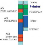
These process line problems must also be handled by operators. Whenever an operator is required, than operator training is required and subjectivity is thus brought into the total quality equation. In the past, an SMT line used to be comprised of three core processes: paste printing, component placement and reflow soldering. Today, the SMT line also involves more demanding monitoring processes to ensure quality (figure 2):
- Solder paste inspection
- Traceability (data matrix code and barcode)
- Placement inspection and control
- Solder joint inspection and
- Electronic final testing
As the first process step, the solder paste printing process must be assigned a key importance for the quality of an SMT production line. Errors that occur here can affect the product in all other process steps, making a correction more expensive as you move down the line – the cost of repairing the component increases with each additional process step.
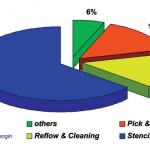
Due to the vast number of factors that influence the printing process, there is a very high share of potential problems which are directly related to this task. According to an analysis by C.H. Mangin (figure 4), the printing process represents the highest risk of error with a 64 % share of all possible causes for defects in the total SMT process. It therefore makes the most sense to monitor and correct problems here at the printing step. 100 % post-print inspection is the only correct way to decrease and/or completely avoid printer related defects. Current studies have shown, however, that only 20 % of SMT production lines have implemented 100 % post print inspection. The logic here is missing.
One reason for this may be budget restrictions. If you are only able to install one inspection system to check one of the key process steps in your SMT line, you will naturally want to inspect the final PCB quality after soldering. While the errors that are detected here can prevent a defective assembly from leaving the factory, they often require very expensive repair procedures. Production management must be aware of the error potential in the printing process. If the budget for a separate post-print inspection system is not available, then the printing machine itself should have an inspection capability integrated. This is a cost-effective alternative and nearly 90 % of the in-line screen printers sold today have this option available.
The performance of integrated inspection systems, however, varies significantly with respect to inspection task and inspection speed. Most systems available in the market can detect the paste on the pad, solder bridging and print alignment. All of these systems, however, share critical disadvantages. None of the integrated inspection systems currently available in the marketplace is able to provide 100 % inspection without delaying the cycle time of the complete production line. The printed substrates can only be partially checked.
It goes without saying that all manufacturers are working intensively to improve their integrated inspection systems. The desire and necessity for a 100 % inspection has not been a secret but rather an all important goal to achieve. Even if the objective is clear to all, however, the methods of achieving it vary.
These include:
- Expanding the field of view
- Quicker movement of the camera axis by using linear drives
- Camera “flashing” when moving and capturing the images
- Reducing the core cycle time permits more time for inspection
- Parallel process of stencil cleaning and inspection
While such activities clearly improve existing concepts, they do not represent real innovations. All too often, equipment manufacturers are so deeply rooted in their core technology that it is almost impossible for them to change them. By taking a step back and viewing the total process from a distance, new ideas can result.
Coming precisely from this vantage point, Ersa approached the inherent problems from a new angle. As a leading manufacturer of soldering systems, the company has been committed to being a true strategic partner for its customers.
The paste printing and reflow soldering processes have the most process overlaps as they are quite dependent upon each other.
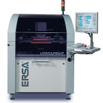
Customers have always wanted to receive process technology from a single source, for example, “an all-round carefree package” for all their SMT line problems. This entails understanding the process and offering system solutions that add value to the customer’s production line. For this manufacturer, developing a screen printer was the logical next step as a strategic systems supplier. The Versaprint screen printer and the integrated revolutionary LIST (Line Scan Technology) for 100 % post print inspection.
LIST – Line scan technology
State-of-the-art in a printing machine up until today has been a system with the camera placed between substrate and stencil. This technology has proven itself and provides the greatest possible precision combined with low cycle times. One limitation with today’s screen printers, however, is the use of area cameras for post-print inspection. Although these cameras are ideally suited for aligning the substrate with the stencil, they have a key disadvantage for inspection – the small field of view (FOV). The mechanical restrictions of the screen printer and method for aligning the substrate and stencil do not permit further expansion with respect to inspection. The limits of this traditional technology have been reached and something new had to be created.
The line sensor camera
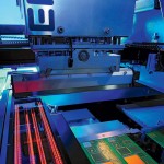
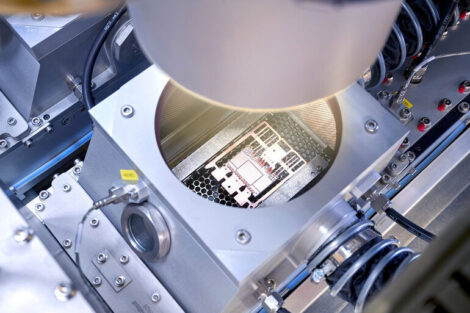
Ersa revolutionizes the alignment and inspection processes via the use of a line sensor based camera for both alignment and inspection (figure 3). Similar to a standard scanner, the LIST camera (patent pending) has top and bottom line sensors. Standard cameras take many pictures of a very small area, whereby the LIST camera scans the entire length of 260 mm at a speed of 35 mm per second. The fastest inspection speed in a printer today is 1,200 mm 2 /sec. The LIST camera in the screen printer achieves a fast inspection speed of 9,100 mm 2 /sec. In addition to inspection speed, the scanning of the entire substrate offers additional advantages with respect to no stretching and the teaching-in of fiducial marks.
The Line scan technology provides comprehensive new functions for image support for the operator during set-up, operation and process optimisation. Quick image capture even for large areas; ideal analysis results through different illumination and analysis tools; and flat determination of position information for perfect alignment; best-possible compensation for substrate offsets; acceleration and automation of teaching processes through complete depiction of the substrate in the software; definition of fiducials, inspection positions without tools directly on the substrate image reflect the main advantages.
This new technology allows the operator to see the complete printed circuit board on the screen. The software permits free definition of the image section across the complete circuit board range. Using a zoom function, it is possible to expand relevant areas for selection and thus to precisely position the fiducial marks and inspection areas. In addition, the “flat capture” of the printed circuit board and template permits innovative alignment processes in order to respond completely automatically to a wide range of problems such as circuit board stretching.
Parallel processing
The use of a line sensor camera substantially enlarges the area that can be inspected and will achieve a cycle time that is quicker than the line cycle for 100 % inspection of the substrate for a wide range of customers. But there are also customers whose line cycle time is under 20 seconds and who want or are obliged to carry out 100 % post-print inspection. For these customers, LIST alone is not enough – a parallel process is necessary. Here too, the company took a new path.
With current screen printers, the substrate is printed first and then inspected. In the Versaprint P1, these two most time consuming steps have been combined for true parallel processing. This is made possible by changing the alignment of the camera axis and using a three-part transport known as a TRT Triple Rail Transport. The resting position of the line sensor camera is at the right exit transport section. It is thereby possible to now completely inspect (100 %) one circuit board whilst printing the next. The parallel inspection with LIST and TRT adds the advantage of effectively disregarding the inspection time from the cycle time as long as it is less than or equal to the printing time. Because this inspection process is essential for each PCB, it can rightly be called a real parallel process.
With the new screen printer, 100 % inspection is now possible in the printing machine and at the cycle speed of the line. This makes the use of an additional AOI inspection machine after printing superfluous. The screen printer not only executes processes, it also supports the operators at their work. The printers of the company take over control functions and assist and guide the operator when executing tasks. A quickly traceable software structure together with online help enables operators to train quickly and obtain safe and repeatable handling. The operators gain time for more detailed monitoring of the individual processes and thus receive the opportunity to optimise the complete process. For example, the systems allows for the option to set the machine offset automatically.
Inspection and GUI
The following inspection functions are possible with the Versaprint: pad coverage, print offset, short circuits, stencil blockages, and unwanted residues and smears on the stencil bottom side. By inspecting the stencil for blockages, unwanted residues and smears, the machine can respond flexibly to the process’ cleaning requirements and thus save cycle time. Stencil cleaning occurs automatically and only released when it is required.
The design of the GUI (Graphic User Interface) is completely in accordance with the E95–1101 SEMI standard. This guarantees the user a quicker and easier learning curve. The machine software concept offers distinct advantages. It is possible to perfectly protect the production process from unauthorised manipulation through the availability of functions and entry fields that can be freely programmed for several user groups. The ability to view and enter can be freely configured for each function and entry field. There are five different entry groups available (operator 1+2, supervisor, maintenance and service).
The printer
This innovative printer takes the pressure off the operator by optimising the printing processes – starting with intuitive setting up of new print programmes via optimised alignment and offset functions for perfect printing right up to high quality inspection parallel to the printing process. Such new technologies as LIST (Line Scan Technology) combined with parallel printing and inspection processes characterise the focus on the core competencies of the printer: time saved through optimised ability to operate, comprehensive automation, shorter cycle times and increased machine functionality. Using the line sensor camera, several data matrix codes or bar codes are read out for each substrate and linked with the SPC data. The read codes are checked by the superior host computer and if necessary the substrate processing is stopped.
Available as options:
- Stencil bottom side cleaning with the 3 mode types: dry, wet and vacuum
- Solder paste dispenser
- Temperature control
- Statistical process data capture
- Recognising and reading bar and data matrix codes
Conclusion
The integration of stencil printing and 100 % inspection into one machine is a key feature of this series of Versaprint machines. LIST provides a level of automation for the printing process that has never been seen before on the market. A constant process quality can now be achieved that is for the most part independent from the operator. The implementation of the GUI in line with the SEMI standard is another feature to increase the process stability.
EPP Europe 424
Share:
