Flexible and rigid-flexible PCBs compensate mechanic fitting tolerances in electronic modules. The designing engineer should make use of this flexibility as early as when designing the flex area. With a special trick you can even get increased flexibility in all three spatial directions.
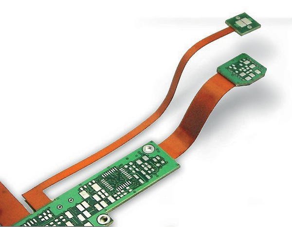
For decades flexible and rigid-flexible PCBs have represented a proven and reliable technology, steadily gaining importance over the years and – according to all forecasts – continuing to gain importance. In the beginning, the focus was on highly reliable systems with priority being given to the connection technology facilitating undetachable connections of several rigid PCBs. Today, flex and rigid-flex technologies are also used for many mobile consumer products, like mobile phones, cameras, etc. In these products, there is often only limited space for electronic parts and electric connections have to be set up through tight openings. One example are sensor heads at the end of thin stainless steel tubes or cannulas. Today, the following factors are crucial when a decision for flex/rigid-flex PCBs is made:
- Decreased weight and height of the module
- Extreme miniaturisation with micro-flexes
- Saving space required for connectors
- Simple integration in flip casings
- Inexpensive roll-to-roll volume manufacturing
- Low loss and defined impedances for high frequency applications
Despite having been established for a long time, inventive developers keep on finding new and ingenious designs to provide FPCs with additional features. Using one of these designer tricks, the outline is designed in a way that does not only increase flexibility but also allows additional degrees of freedom for the flexibility of the PCB.
More degrees of freedom for movement
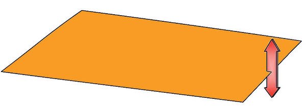
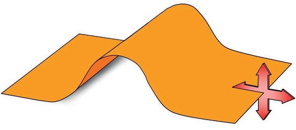
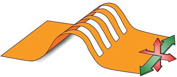
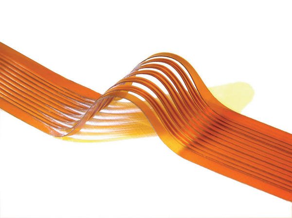
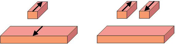
Normally, the end of an FPC can only be warped vertically to the foil layer, i.e. in z direction. Movement in x/y direction is almost impossible due to the material’s low elasticity. If the flex conductor is provided with a length reserve by mounting it with an upward bulge, the PCB can move into another dimension: The length of the connection can now vary. This configuration thus facilitates movement in longitudinal direction. The flexibility of the end of the foil into the third spatial dimension is nevertheless rather weakly developed as unacceptably small bending radii can easily form at the edges of the bulge. This might prevent a permanently reliable connection. In order to obtain more flexibility also in the third dimension, the foils can be cut longitudinally in the bulged area. The resulting thin strips can then twist and move against each other so that a stronger lateral movement of the ends of the foil becomes possible.
Full flexibility of 3D flexes
Cuts made by laser are especially beneficial as these can be made without loss of material. This means that in total the entire flex width is available for the design. Only the area surrounding the laser cuts has to be kept free from the conductive pattern. Depending on layout and size of the foil circuits, 0.05 to 0.3 mm around the cutting area have to be kept free.
Special configuration for impedance flexes
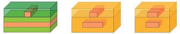
Good signal integrity has to be arranged for, and not only in the giga hertz range. For circuits from approx. 300 MHz the impedances of the conductors have to be adapted to the requirements of the active components in order to limit signal disturbances and loss. For the transmission of RF signals via flexible areas of a circuit, PCB tracks with a defined impedance can be implemented. Compared to FR4, adhesiveless foil material has the additional advantage of significantly lower loss of tan (d) = 0.007 and a dielectric value of er = 3.4. FPCs with a defined impedance – so-called impedance flexes – are often manufactured with 100 µm basic material in order to be able to implement the usual impedances with reasonable structure widths. Both the single-line configuration and differential signals can be layouted on double-sided impedance flexes, with one layer containing the signal lines and the other layer serving as a reference layer. Between the signal lines, additional reference lines can be laid to reduce crosstalk between the channels. Due to the copper surfaces the mechanic behaviour of impedance flexes becomes less elastic. Instead, a plastic share is added. This means that these flex PCBs largely retain their assumed shape after forming. Rastered reference planes can counter this to a limited extent. For manufacturing reasons this used to be recommended in the past, but is no longer necessary today. For EMC reasons three-layer flex connectors are sometimes demanded, whose signal conductors are positioned on the middle layer between the external shielding layers. These FPCs are rather unusual in combination with defined impedances as this configuration requires an even larger layer spacing. The resulting total thickness of the PCB of approx. 0.4 to 0.8 mm significantly reduces its flexibility. Single-sided impedance flexes with co-planar reference layers on both sides of the signal conductor are also highly unusual as the spacing of the signal conductor to the reference conductors is under 100 µm. For this reason impedance flexes generally have a double-sided structure and are thus not suitable for a permanent dynamic bending load.
Line adaptation in 3D flex design
For rigid PCBs with extensive reference layers the suitable conductor width can easily be calculated using 2D FEM simulation. However, for narrow PCBs – as well as for the incised flex connectors using 3D flex design – it also has to be taken into consideration that the reference layer is narrower as well. The reduced capacitive interconnection of both potentials leads to an increase in impedance. Thus, the width of the signal conductor has to be adapted to achieve the right impedance. As there is a large number of layout variants and materials for the design of flexible, rigid-flexible and impedance-flexible PCBs, a close co-operation of the customer with the PCB manufacturer is essential as early as in the development stage to find an optimal and integrated solution for design and manufacturing. Contrary to the prior assumption that FPCs are generally too expensive it is thus possible to optimise costs and to keep overall costs low.
EPP Europe 419
zusammenfassung
Flexible und starrflexible Leiterplatten gleichen mechanische Einbau-Toleranzen in Baugruppen aus. Bereits im Design des Flex-Bereichs sollte der Konstrukteur sich diese Beweglichkeit zu Nutze machen. Mit einem besonderen Trick erhält man sogar erhöhte Flexibilität in allen drei Raumrichtungen.
Des circuits imprimés flex et flex-rigides compensent les tolérances de montage mécaniques des composants. Dès la conception de la zone flex, le constructeur devrait tirer parti de cette mobilité. Grâce à une technique particulière, il est même possible d’obtenir une haute flexibilité dans les trois dimensions.
Dei circuiti stampati flessibili e rigido-flessibili compensano le tolleranze costruttive meccaniche nei gruppi costruttivi. Già in fase di progettazione della parte flessibile il costruttore dovrebbe sfruttare questa mobilità. Grazie ad un accorgimento è possibile ottenere una maggiore flessibilità addirittura nelle tre direzioni.
Share:


