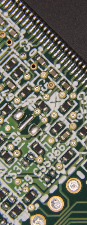
Reflow soldering is the workhorse of modern SMT production. Whether applied to simple consumer boards or complex multi-layer substrates carrying fine-pitch BGAs and 0201 passives, the process follows the same fundamental principle: a pre-deposited solder paste is heated in a controlled thermal sequence until the alloy melts, wets the metallised surfaces and, upon cooling, forms a mechanically and electrically reliable joint. Despite its apparent simplicity, the process encompasses intricate interactions between alloy chemistry, flux activation kinetics, component thermal mass, substrate properties and oven atmosphere — all of which must be balanced to keep defect rates within acceptable limits.
For process engineers entering the field or revisiting foundational knowledge, a structured understanding of how a reflow oven works, how profiles are designed and why certain defects arise provides the framework necessary to make informed decisions about equipment selection, paste qualification and process optimisation.
How a Convection Reflow Oven Operates
The predominant heating technology in contemporary reflow ovens is forced convection. Heated air or nitrogen is circulated at controlled velocity through a series of discrete thermal zones, typically ranging from seven to twelve zones in production-grade systems. The board assembly travels through these zones on a conveyor at a set belt speed, which — combined with the individual zone temperatures — determines the time-temperature profile experienced by any point on the assembly.
Zone count matters because it determines profile flexibility. A higher zone count allows finer independent control over heating and cooling ramps, making it easier to accommodate assemblies with highly disparate component thermal masses on the same board. Some systems incorporate a dedicated cooling zone using chilled air or water-cooled heat exchangers to control the solidification rate of the alloy, which influences grain structure and joint ductility.
Nitrogen atmosphere capability is a further equipment variable. Operating with oxygen levels below approximately 100 ppm reduces oxidation of molten solder and board metallisations, improving wetting on difficult surfaces and enabling the use of low-residue, no-clean pastes at reduced flux loading. The trade-off is gas consumption cost and the engineering overhead of maintaining oven seal integrity.
Anatomy of a Reflow Profile
A standard reflow profile is conventionally divided into four stages: preheat, soak (also called thermal equalisation), reflow and cooling. Each stage serves a distinct metallurgical or chemical purpose, and the boundaries between them are defined by temperature ramp rates and dwell times rather than by fixed absolute temperatures alone.
During preheat, the assembly ramps from ambient to a soak temperature — typically in the range of 150 °C to 180 °C for standard Sn-Ag-Cu (SAC) alloys — at a controlled rate, generally not exceeding 3 °C per second to avoid thermal shock to ceramic components and to allow solvents within the paste to evaporate gradually rather than violently. Rapid solvent outgassing during preheat is a primary driver of solder balling and spattering defects.
The soak stage allows thermal equilibration across the assembly, reducing the delta-T between large thermal-mass components and small ones before the alloy melts. It also provides the window during which flux activators chemically reduce surface oxides on both solder particles and pad metallisations. Soak duration and temperature ceiling must be matched to the flux system: too short a soak leaves oxides unreduced; too long a soak exhausts flux activity before the reflow peak is reached, leading to poor wetting. The reflow stage itself carries the assembly above the alloy liquidus — approximately 217 °C for SAC305 — for a controlled time above liquidus (TAL), typically 45 to 90 seconds, allowing full coalescence, wetting and intermetallic compound formation. The cooling ramp then controls solidification.
Alloy Solidification and Intermetallic Formation
When molten SAC alloy contacts copper pad metallisation, a thin layer of intermetallic compounds (IMCs) — primarily Cu6Sn5 and Cu3Sn — forms at the interface through solid-liquid diffusion. This IMC layer is integral to joint formation; without it, there is no metallurgical bond. However, excessive IMC growth, driven by prolonged time above liquidus or by thermal ageing during service life, embrittles the joint. Controlling TAL is therefore not merely a flux management concern but a fundamental joint reliability consideration.
Cooling rate influences the resulting grain structure of the bulk solder. Faster cooling produces a finer microstructure with more grain boundaries, which generally correlates with improved fatigue resistance under thermal cycling. However, cooling rates that are too aggressive risk generating thermal gradients sufficient to crack brittle components such as multilayer ceramic capacitors (MLCCs). For most SAC assemblies, a controlled cooling rate in the range of 3 to 6 °C per second is considered a practical compromise.
Common Defect Mechanisms and Their Root Causes
Tombstoning — where a passive component stands upright on one termination — results from an imbalance of surface tension forces during reflow. It occurs most frequently on small components (0402 and below) when one pad reaches liquidus before the other, causing the molten solder on the early-wetting side to pull the component vertical. Contributing factors include asymmetric pad design, uneven solder paste deposition and thermal gradients across the component footprint. Profile adjustments that slow the approach to liquidus — effectively extending the soak — reduce the wetting imbalance and suppress tombstoning frequency.
Head-in-pillow (HiP) defects on BGA and CSP components arise when the board-side solder paste and the component-side ball do not fully coalesce during reflow, leaving a non-wetted interface that retains a characteristic dimpled appearance under X-ray inspection. Warpage of the package substrate during heating lifts the ball away from the paste deposit at the critical moment when both surfaces are molten. Mitigation strategies include profile adjustment to match the warpage behaviour of the specific package, pad size optimisation and, in severe cases, selection of a lower peak temperature alloy for the paste. Voids, solder bridges and non-wets each trace to distinct root causes — paste volume, flux activity, pad contamination or profile parameters — underscoring that systematic defect analysis must address material, design and process variables in combination.
Profile Characterisation and Process Window Definition
Profiling is performed using thermocouple data loggers attached directly to representative assemblies. Thermocouples are affixed at locations identified as thermal extremes: the coldest point (typically a large component or heavily copper-poured zone) and the hottest point (typically a small passive or board edge). The process engineer must ensure that the coldest point reaches the minimum required reflow temperature while the hottest point does not exceed the component manufacturer's maximum rated temperature — a constraint that defines the available process window.
Process window index (PWI) is a dimensionless metric used to quantify how well a given profile fits within the specification limits of all components simultaneously. A PWI below 100 % indicates the profile is within specification; the lower the PWI, the greater the safety margin. Regular profile verification — particularly after product changeovers, paste lot changes or oven maintenance — is considered best practice in high-reliability manufacturing environments and is frequently mandated by quality standards such as IPC-7530.
Practical Considerations and Outlook
As component miniaturisation advances toward 01005 and smaller package dimensions, and as heterogeneous assemblies combining standard SMD components with embedded dies or advanced packages become more common, reflow process windows will narrow further. The increasing prevalence of lead-free alloy variants beyond SAC305 — including low-silver alloys for cost reduction and high-reliability alloys with added dopants for improved thermal-cycle performance — means that profile knowledge cannot be transferred generically across paste systems without revalidation.
Closed-loop oven control systems that use real-time thermal sensing to compensate for production variation — changes in board loading density, ambient temperature shifts or zone heater ageing — represent the direction of ongoing equipment development. Coupled with statistical process control applied to profile data and inline SPI and AOI feedback, these capabilities move reflow soldering from a craft-based activity toward a data-driven, continuously optimised process. The fundamentals of thermal physics and alloy metallurgy, however, remain constant and continue to provide the analytical foundation upon which every process decision must rest.