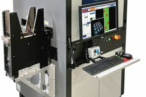
For years, AOI has suffered from a need of high maintenance to keep false calls and false accepts under tight control and from a lack of coverage when some defects were not detectable by the equipment. With modern 3D technology, images contain additional information to build more efficient and reliable tests but also to add more inspection capabilities such as coplanarity, lifted leads, or solder joints. Facing a wide offer in a very dynamic market, with slightly different technologies and performances, electronics manufacturers, through their process engineers, need to focus on key characteristics to select the optimum equipment for their particular needs.
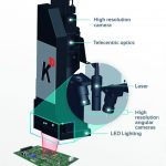
Most of the 3D AOI systems are using a technology called triangulation sensing which measures the height of components, joints, or leads. Basically, the light source (projector) and the camera are placed apart at a defined angle. To make it simple, the displacement of the light gives the height of the object. For the light source, there are two types of technology applied. One uses structured light that is called Moiré technology and the other uses a laser beam known as laser technology. Some vendors like to use just one top-down camera coupled with a few angled projectors, others rather use a top-down projector coupled with angled cameras.
Inspection coverage
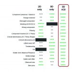
If all 3D inspection systems are offering the same verification coverage, the solution often reflects on the technology background of the vendor. The suppliers that have developed 3D AOI upon their 3D SPI basis technology, will have the original full 3D only approach completed with some 2D ad-ons. On the other hand, companies that have long-term experiences with 2D AOI, have used their strong 2D base to build more powerful 3D technology. Today, combining both technologies 2D and 3D, and not only using one of the two, is the only method to offer the best inspection coverage.
For the first time in the 20 years since the start of automated inspection technology, modern AOI can now provide a very comprehensive test coverage while drastically reducing false calls and eliminating all false accepts. The matrix shows that when combining the better of the two AOI technologies, it will provide the best results and inspection coverage. Even though 3D technologies enhance the examination coverage, some drawbacks may impact their ability to perform on any application.
Shadow effects
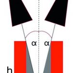
With components heights ranging from 1 mm to 25 mm, angles between cameras and projectors are creating shadows at the feet of the tallest components that can hide smaller components from 3D reconstruction. The magnitude is directly dependent on the angle between sensors (cameras, projectors) as shown in the scheme of the principle.
The more open the angle (α) is, the wider the shadow area is. Depending on the technology integrated into the system, the area can be double its size, shadowing an area of up to 14 mm around tall components. It can totally or partially impact the inspection coverage of the surrounded components. All these shadowed components won‘t be covered by any of the 3D tools and the verification of the assembled PCB won‘t be the best. Only 2D tools will be applied under these circumstances, however, if one component is slightly tilted or if some leads are lifted, these will not be detected. For applications in critical high-volume manufacturing environments, such as in the automotive, mobile devices, or other various industries, mixing tall, small, and leaded components, these criteria must be checked to ensure the best 3D coverage.
PCB/component referencing
When a system makes measurements, particular attention should be placed on the referencing system. 3D AOI systems, like 3D SPI, offer a range of different technologies to ensure the precise zero reference. Would it be more accurate to have references close to the components or global references placed on the PCB? There is no straight answer, as every location is unique and in some cases, local references work better than global ones and vice-versa. The viable solution is to combine both methods, define references across the PCB and use only the best for each location or reference designator. This strategy attributes automatically hundreds of references on the PCB itself surrounding all the components.
Depth of Z-measurement
When executing 3D imaging, one of the crucial parameters is the range of heights measured by the system. Contrary to SPI, where measured heights never exceed 1 mm, AOI at board level is facing a challenge with very small volumes of solder joints, and tall components, or relatively large connectors. Most of the 3D systems struggle when it comes to having a wide range of measurements, and whether there is enough resolution, or not, to measure joints. That‘s the reason why some AOI systems are using a threshold, from about 3 mm to 5 mm, above which 3D measurement is deactivated and component heights exceeding this threshold are covered only by 2D technology. This issue is overcome by vendors using laser lighting technologies. They offer a complete range of measurements from 0 to 25 mm, while other suppliers, using Moiré lighting technology, may offer solutions using a complex, difficult to maintain, and expensive optical head.
Measurement accuracy
With upcoming Industry 4.0 strategies getting into most of the manufacturing floors, the need of line connectivity and feedback loops to achieve zero defect manufacture is driving AOI and SPI system suppliers to develop repeatable and highly accurate solutions. This is becoming critical with the miniaturization of components that are becoming smaller and smaller. Within Industry 4.0 concepts, a feedback loop to the P&P equipment in the line is a key contribution of AOI systems with exact X, Y and theta measurements. For years now, 2D technology has had a proven record of accuracy and repeatability of component location. However, 3D technology has not yet reached the level of accuracy and repeatability of the old systems. AOI systems using only 3D technology to locate and measure components may suffer from a lack of this.
With GR&R ranging from 10 % to 30 %, most of the systems are not capable of feedback measurements to correct the alignment of the placement machine. Some AOI systems are using 2D technology to accurately locate component placement positions, while 3D is dedicated to other potential defect issues, such as coplanarity or solder joints. These systems have maintained the same levels of accuracy and repeatability featuring GR&R within 10 %. Therefore, while looking for integrated solutions compatible with Industry 4.0 strategies, process engineers have to integrate GR&R tests in their benchmark to ensure this capability.
Conclusion
If almost all 3D AOI systems offer the same inspection coverage, the main differentiator is the ability to maintain this coverage in all types of possible applications and configurations. With discrepancies, in terms of shadows, Z-range, and accuracy, some of them may not be suitable for a company‘s SMT line. Therefore, considering the investment consent by teams to select equipment, it becomes important to integrate these key parameters in the benchmark process.
Zusammenfassung
Automatische Inspektionstechniken (AOI) sind seit mehr als 20 Jahren in der Elektronikfertigung eingeführt, erst zögerlich und nun praktisch flächendeckend. Ein wertvolles Werkzeug für die Qualitätssicherung, Produktionsoptimierung sowie Defektminimierung. Neben der Pasteninspektion (SPI) kommt der Überprüfung der bestückten Baugruppe mittels 2D/3D-AOI sehr hohe Bedeutung zu. Oft, aber nicht immer, sind die Ergebnisse der dazu verwendeten Inspektionssysteme ähnlich. Allerdings gibt es Vor- und Nachteile abhängig von der Aufgabe. Deswegen müssen Anwender sorgfältig evaluieren, welche Lösung für sie die am besten geeignete ist.
Résumé
Les techniques d’inspection automatique ont été introduite il y a maintenant plus de 20 ans dans la fabrication électronique, initialement d’une manière hésitante, mais à présent en couvrant toute les domaines. Un outil important pour l‘assurance de la qualité, l‘optimisation de la production, et la minimisation des défauts. En plus de l‘inspection de la pâte à braser (SPI), la vérification de l‘assemblage monté en utilisant AOI 2D / 3D est d‘une grande importance. Souvent, mais pas toujours, les résultats des systèmes d‘inspection utilisés à cette fin sont similaires. Cependant, il y a des avantages et des inconvénients en fonction du travail à effectuer. Par conséquent, les utilisateurs doivent soigneusement évaluer quelle est la solution la plus appropriée pour eux.
Резюме
Системы оптического контроля качества печатных плат (AOI) начали применяться на производстве электроники более 20 лет назад. Поначалу с некоторой долей осторожности, а затем практически повсеместно. Действительно ценный инструмент для обеспечения качества, оптимизации продукции и снижения количества брака. Наряду с контролем нанесения паяльной пасты (SPI) проверке комплектных узлов с применением двух- или трехмерных систем оптического контроля придается все большее значение. Однако не всегда результаты применяемых систем контроля одинаковы. В зависимости от задачи каждая система имеет свои преимущества и недостатки. Поэтому пользователи должны тщательно взвесить все факторы, чтобы понять, какое решение будет для них наиболее оптимальным.
