Since its standardization in 1990, boundary-scan (BS) technology has become increasingly adopted within the industry. It’s now a mainstream test strategy for high-complex chips, boards and entire systems. But all is not sweetness and light – this standard IEEE1149.1 has built-in limitations which are real handicaps in practical use. Here we highlight the most pressing limits and present an approach resolving the problem of fine diagnosis.
Thomas Wenzel, Goepel Electronics
Undoubtedly, BS is one of the most innovative test strategies to have been introduced to the market in the last ten years. However, practical experience gained during this time has lead to an intense discussion about the limits of this technology. In the following, we will characterize the particular points for which it is necessary to find an answer.
In principle, BS is a static digital in-circuit test. Thus, dynamic faults cannot be detected. Possible approaches to this problem include a combination of BS with functional test and the use of hierarchical BIST (build-in self test). Being a digital test process, IEEE1149.1 cannot directly verify analog structures. In practice, this problem is solved by combination with other test methods such as using MDA (manufacturing defects analyzer) or flying-probe machine. The current state-of-the-art is to establish a limited analog-cluster test using purely digital resources. The increasing use of IEEE1149.4 is expected to improve on this.
A problem which is often mentioned is the ground-bounce phenomenon in ICs and consequently in the measuring system. Many BS-test instruments have evolved adequate features to suppress ground bounce. In practice, there is some difficulty in clearly analyzing defects and pinpointing a fault sufficiently well to issue a definitive repair instruction. This is particularly true for problems relating to a defective test bus as well as faults arising in cluster and connection tests. Whereas various solutions already exist for the ground-bounce trouble, there is no clear answer yet to the last point.
The problem of fine diagnosis via BS
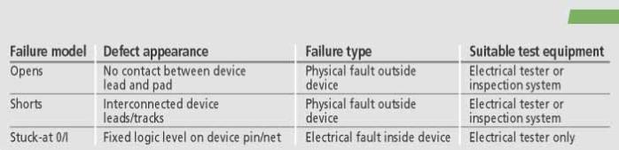
In the test department, three different main error types are modeled during the generation of test vectors to verify electronic circuits for assembly-related faults (table 1).
From the point of view of production-related faults, we assume that these failure types arise at component pins through the assembly processes, and have not been brought in or caused by external events. Design errors already existing before placement/insertion which can be recognized as dynamic failures during functional test, bare-board or component defects, are not considered here.
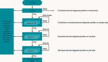
The ability of test vectors to stimulate a defect ensures an appropriate high-fault coverage in Go/No-Go testing. However, this gives no indication of the cause of the defects, which is needed for the generation of a clear repair instruction. For this, an effective diagnosis strategy is indispensable (figure 1).
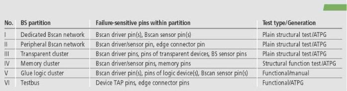
A mix of specific electrical tests, visual inspection, ad-hoc analysis measures and the knowledge of specialists is typically applied in the diagnosis procedure. The extend of diagnosis strategy (quality and in-depth) depends on the electrical and physical attributes of a board assembly. Here, the ability to functionally partition a board plays a decisive role, because the diagnostics effort grows exponentially with the number of elements contained in such a partition. This is the reason why functional tests offer very good fault coverage, but the quality of diagnosis is relatively low. In contrast, as we can see from figure 2, BS partitions a circuit naturally into separately testable structures.
Because BS is a structural test technique, most vectors can be supplied by automated test-pattern generation (ATPG), offering fault coverage of up to 100% for production-related defects. The only exception is the test of glue-logic clusters, and IEEE1149.1 is not alone in its suffering from this familiar test problem. Nevertheless, it is difficult to escape the fact that, typically, BS cannot answer the question of pin-precise fine diagnosis (figure 2).
Diagnosis is generally limited to net level, and will need (see figure 1) an appropriate diagnosis strategy to achieve pin-level qualification. In the past, visual inspection was often used to localize a faulty pin connection. The increasing use of BGA and CSP packages renders this strategy impractical even for low pin-count devices. Therefore, in practice, a field-array device such as a BGA is typically replaced using trial-and-error, or it is inspected by an expensive X-ray system. Bearing this in mind, it is easy to understand the search for an alternative, more economical solution.
Next-generation testers to solve the problem
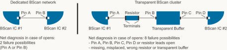
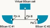
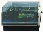
To improve diagnostic results, Goepel has developed the next generation of diagnostic boundary-scan tester in co-operation with some key customers. This tester, Scantury Prober (figure 3), has been in development for two years. The fine diagnosis is enhanced by the idea of combining boundary scan with a flying prober. The temporary introduction of a virtual BS-pin into a faulty network makes it possible to make a fine diagnosis of where the fault lies among the various devices on the net (figure 4). This pin must have the ability to provide backdriving/nodeforcing and must be able to drive and measure simultaneously.
Assuming that there is access to contact the net, the following diagnostic possibilities arise for the first four basic defects from table 1: opens – can be 100%-diagnosed for all categories at pin level; shorts – BS-networks of categories I and II can be diagnosed in the case of shorts to non-scan networks. Where access to layout data is available and assuming shorts only appear between neighboring pins, a pin-level diagnosis is partly possible. Shorts between non-scan pins within transparent clusters are typically only diagnosable at net level. In case of stuck-at 0/I – where all pins are connected in parallel, these defects are only diagnosable at net level
This development represents a tremendous degree of progress particularly for the detection of open-circuit failures. A combination with different techniques such as AOI and analog measuring using a flying probe allows the quality of diagnosis to be further significantly improved for shorts. This is why intelligent multi-mode-diagnosis equipment is in great demand. The Scantury Prober, which combines BS-tests, mechanical probing and AOI (figure 5), probes the board with a precision better than 50µm, giving access to even very fine structures.
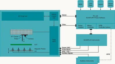
To further increase the fixtureless nature of this solution, up to twelve magnetically fixed probes can be attached to a driven platform to make contact with the UUT (unit under test) from below. These probes are primarily intended to supply power and test-bus signals. All probe signals can be switched to an external connector using an integrated multiplexer. The desktop system is controlled (via RS-232) by a PC in which a frame grabber and the BS-controller are located. The voltage-programmable signals for probe and test bus are provided by external Scanplus modules.
The software consists of three components in total: Cascon Galaxy, a program package for BS-tests with the probe; OptiCon, a remotely controlled program for automated optical inspection; and an overall control-software package, including intelligent diagnosis algorithms to synchronize the functions of the various instruments.
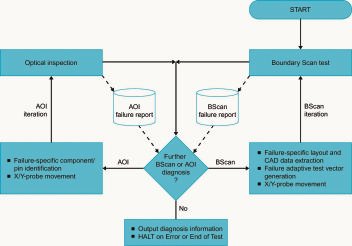
This system architecture effects a failure-adaptive diagnosis strategy of the tester in the interplay between standard BS-test, BS-test with extended probing and AOI (figure 6). Here, AOI is used for a clear diagnosis of component-related defects such as missing, insufficiently soldered parts, etc., and the detection of unsoldered pins as far as visible. Thus, the unit becomes a direct process sensor. In the case of field-array packages, this task is taken over by X-ray systems. By including optional instruments such as DMM, frequency meter or DSO per IEC-Bus/GPIB for instance, the unit can application-specifically be extended to perform more automated tests and increase its efficiency.
An outlook
Even though BS, with its test-partitioning approach, offers a far better basis for effective fault coverage and localisation than traditional techniques, it doesn’t automatically solve the problem of pin-precise fine diagnosis. The trend towards flipped packages with pins located under the semiconductor die makes optical inspection impossible and hinders diagnosis even more. The newly designed instrument solves this issue by the temporary introduction of an additional BS-pin to give increased virtual testability. The addition of layout information in combination with electrical and optical instruments allows an intelligent failure-adaptive diagnosis strategy. Thus, the efficiency of the repair process is enormously increased. Because the method covers electrical fault models and because of its efficient product handling, at this point is has many advantages over other methods such as X-ray.
In the course of further sys-tem development, improvements in addressing fine diagnosis for test-bus faults and defects in glue-logic clusters are planned. Because of its open architecture, the tester can also be used for other verification purposes in laboratory and production. This way, the tool will be even more economically used, and the time to break-even for this next-generation multimode-diagnosis tester will be even shorter.
ZUSAMMENFASSUNG
Diese Lösung für den Baugruppentest hat etwas Bestechendes: Man nehme bewärte Boundary-Scan-Technik, erweitert um einen virtuellen Testpin, und kombiniere dazu eine Flying-Probe. Damit man auch bestimmte Bestückungsfehler und ungenügende Lötstellen erkennen kann, soweit sie optisch zugänglich sind, packt man noch ein AOI-System dazu. Der unerfüllbare Wunschtraum vieler Anwender ? Nein, ein clever entwickeltes Testsystem, jetzt bei uns exklusiv erstmals vorgestellt.
RÉSUMÉ
Cette solution pour le test des cartes est séduisante : prenez la technique éprouvée du boundary-scan, complétez-la par un testpin virtuel et combinez-lui un flying-probe. Pour reconnaître également des erreurs d’implantation précises et des soudures insuffisantes, ajoutez au tout un système AOI. Non, il ne s’agit pas du rêve inaccessible de nombreux utilisateurs, mais d’un système de test intelligent que nous présentons pour la première fois en exclusivité.
SOMMARIO
Questa soluzione per il test dei componenti costruttivi ha un qualcosa di seducente: basti pensare all’affermata tecnica Boundary-Scan, ampliata di un pin di test virtuale, e alla combinazione di un provino Flying. Al fine di poter individuare tempestivamente anche determinati errori di connessione e punti di saldatura eventualmente scarsi, purché siano accessibili all’occhio umano, vi si combina in via supplementare anche un sistema AOI. Il sogno inesaudibile di molti utenti ? No, un sistema di test sviluppato con astuzia, adesso presentato da noi per la prima volta in esclusiva.
Share:


