
Today, 008/004” (0201M) components and micro-LED devices are becoming mainstream, with pad and component spacing designs becoming increasingly aggressive. The need to introduce Type-6 powder to the manufacturing floor is becoming ever more necessary.
Our experiment, detailed below, compared solder paste printing of Type-6 powder using two methods: exposed atmosphere versus sealed chamber (non-exposed) to determine the best application method in a production environment. Previous tests have been performed on sealed chambers, comparing print results to blades. The results have shown that, when all things are equal, sealed chambers produce similar results to blades. The question is, however, can those results be sustained over time? Here, we look at which application method delivers the most consistent results over a simulated production shift.
An identical test setup utilizing Solder Paste Inspection (SPI) gathered data to monitor targeted components. This was analyzed to reveal the advantages of either method. A blind test was conducted with two samples of Type-6 paste from different vendors, using a 29” x 29” laser, fine grain stencil with a thickness of 0.002” (0.0254 mm). The test consisted of a four-to-five-hour continuous run with a minimum total board count of 250 substrates. The results will be analyzed to determine which method yields the least defects, waste, and consistency over time.
Type-6 powder/paste
Type-6 powder was originally developed with dispensing in mind. One of the first instances of Type-6 solder paste printing being used in production took place in 2004 within a semiconductor process that applied a 35 um thick stencil (leading edge at the time). The paste and stencil were sourced from Japan, where the formulations were O/A based fluxes and extremely volatile, with a dependable stencil life of only 2 hours.
Type-6 pastes have come a long way in 20 years, but they are still a rare commodity. Due to the limited shelf life, Type-6 paste is not stocked and is produced on demand. One should plan/order well ahead of time to avoid delays as yields to produce this powder improve, the price will most likely move lower. Both price and availability should be taken into consideration when introducing this material to your process.
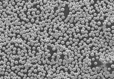
Type-6 powder is defined as spheres that gather at a +635 mesh and a ball size range of 15–5 um, basically any ball diameter less than 15um. Two important issues with Type-6 paste are the surface area and oxide density of the individual balls.
The oxide density that surrounds the individual balls has a thickness range of 1–2 um present regardless of the ball size. This means that the density of the oxides coating on a 45 um ball is the same on a 5 um ball.
The average shelf life of Type-6 paste is eight weeks refrigerated and two weeks at ambient temperature. This will vary with different vendors and chemistry. Paste observed stored past the limit has exhibited flux separation while refrigeration slows but does not stop the interaction of flux and metal. Eventually the flux becomes ineffective.
Cleaning Type-6 paste is more difficult. Once the paste has been exposed to repeated print cycles and exposure, the paste can become stiff in texture. This texture and increased tack make it more difficult to remove this material. A compatible solvent should be considered in the under stencil cleaning process, as dry wiping alone won’t address this flux. Cleaning the stencils and substrates with an ultrasonic cleaner is also recommended as hand cleaning Type-6 paste is very difficult.
Sealed chamber for fine powder
When deciding to use a sealed chamber rather than blades, the following should be taken into consideration:
- Cost savings: Depending on quantity, the price of Type-6 paste can be, 3–8 times more than the average cost of Type-4 paste. Waste with blades can range from 30 % to 70 %, depending on paste type and how closely you monitor this process. The claimed waste on a sealed chamber is 5 %. All things being equal, this is where this option could have its biggest impact. One thing that a sealed chamber can do that blades cannot is keep the same paste in play for several days.
- Consistency of results: The condition of the paste affects both the printer and the reflow when exposed to the environment. The overall rheology of the paste can change over time, resulting in defects where the flux strength can also undergo changes that may affect how well it performs in the oven. Protecting the material in a chamber eliminates this variable from the process.
- Pressure control: With Type-6 paste comes thin stencils. Stencil thickness approaches 25 µm, which is equivalent to household aluminum foil. Combining this with aperture openings which have been reduced to 60 µm, it becomes a challenge to deliver the correct amount of material. For example, when printing on a development board, the correct squeegee pressure is 15 lbs of force on the blades. On the same board, the correct chamber pressure is set to 1.4 lbs. In this case, a ten-to-one ratio of squeegee force versus chamber pressure is used to achieve the same fluid pressure being applied to the same aperture. The sealed chamber has better control of the pressure, where even a change of a tenth of a pound can have an impact on the results.
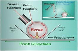
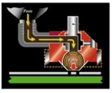
- Aperture fill: Even the first-generation chambers did a superior job on paste-in-hole applications. This is due to the combination of the paste rolling and the extrusion of the paste straight up/down as opposed to an angular laminar flow of the paste with blades during aperture fill. This same combination may help with small apertures as well.
A cover can be put on the sealed chamber at the end of production, and the next day printing can continue using the same material. The storage life of sealed chambers is identical to the material’s stated specification for storage at ambient temperature, which averages about two weeks. However, we have seen Type-6 and Type-7 pastes are prone to settling and to flux separation at ambient temperatures. It is recommended that, if the sealed chamber is not being used for more than a week, the paste should be removed. Refrigeration is not recommended for storing sealed chambers as this is to slow the reaction between the metal and the flux but can accelerate separation.
Test objective & description
The objective of the test was to examine which application method, squeegee blades or sealed chamber, produced the steadier state process over time when using Type-6 paste. Volume data was examined as this is the best indicator of transfer efficiency between the substrate, stencil, and paste. The data examination focused on the standard deviation of the individual aperture groups to see which application method has the tightest spread and delivers the most on-target results. Standard deviation was used to determine the overall performance of the individual component groups. The testing was limited to two paste vendors due to costs and material availability.
Each material was tested individually and sequentially using both blades and a sealed chamber. Each test consisted of a minimum of 250 substrates, printed over a four-to-five-hour time frame. A sampling for SPI was taken every tenth board for a total of 25 data points per test.
Equipment
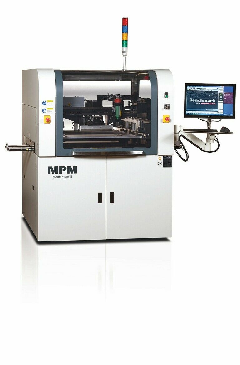
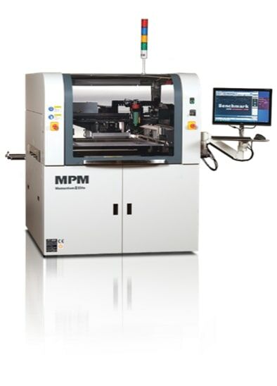
The printing machine used was the ITW/EAE Momentum Elite with a wet print accuracy of
20 microns @ 6 sigma, CpK ≥ 2.0 with an alignment repeatability of ±11 microns @ 6 sigma, CpK ≥2.0, calibrated and verified at CeTaQ. The options used were EdgeLoc+ and Paste Height Monitor.
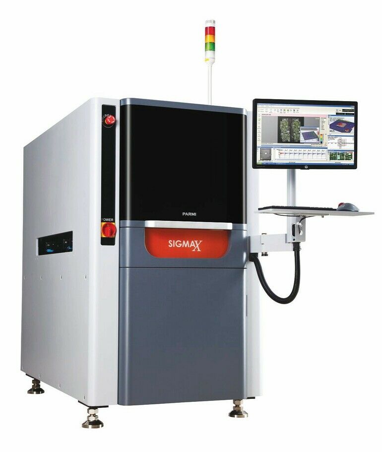
The SPI was the Parmi – Parmi Sigma X SPI with the following specifications:
- X – Y Resolution (um): 7 x 7
- Height, Area, and Volume Repeatability: 3 Sigma 1um, on certified target
- Height Accuracy: 2 um, on a certified target
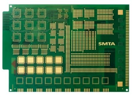
The PCB used for this experiment was the SMTA miniaturization test vehicle with board dimensions of 8.0” (203 mm) in X and 5.5” (139.7 mm) in Y with a thickness of 0.062” (1.57mm). There were approximately 400 pads per board with 200 positioned at 0 degrees and 200 pads positioned at 90 degrees. The 008004” (0201mm) pads were 0.005” x 0.006” (0.127 x 0.1524 mm) with an air gap between pads of 0.0047” (1.1938 mm) and a component pitch of 0.00126” (0.032 mm)
The stencil had a 29” x 29” frame size, high tension, laser cut with nano-coating. Aperture sizes were one to one matching the pad sizes.
We used a dedicated aluminum tooling plate – vacuum was available but was not required during testing – substrates were held in position utilizing side-snugging.
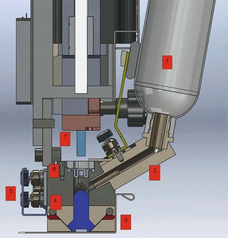
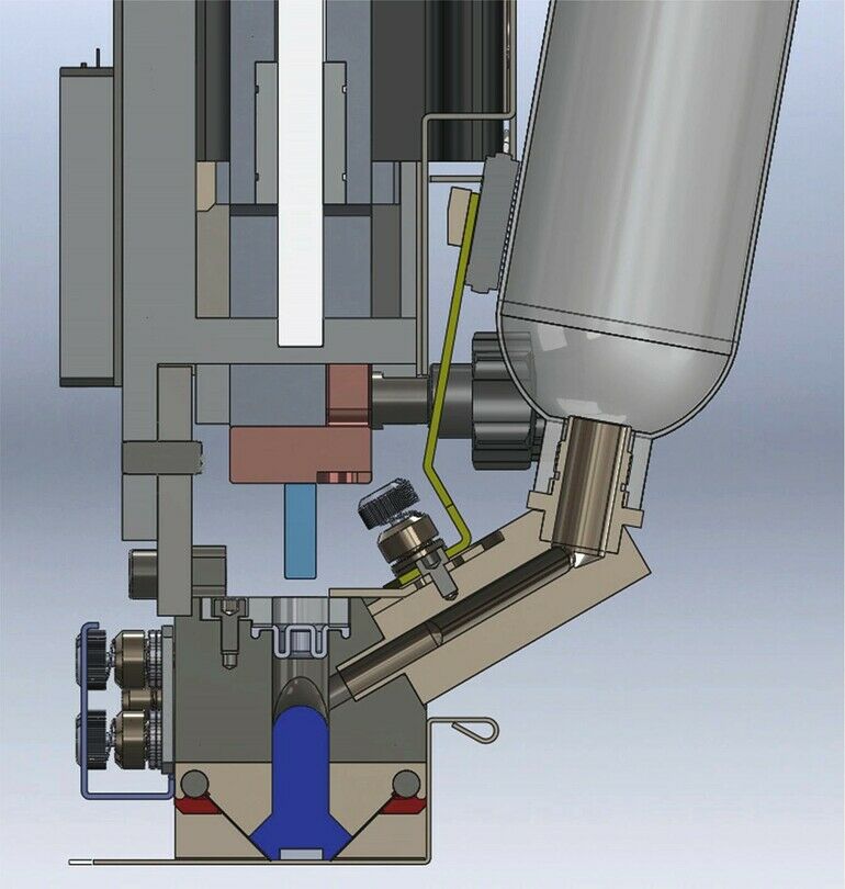
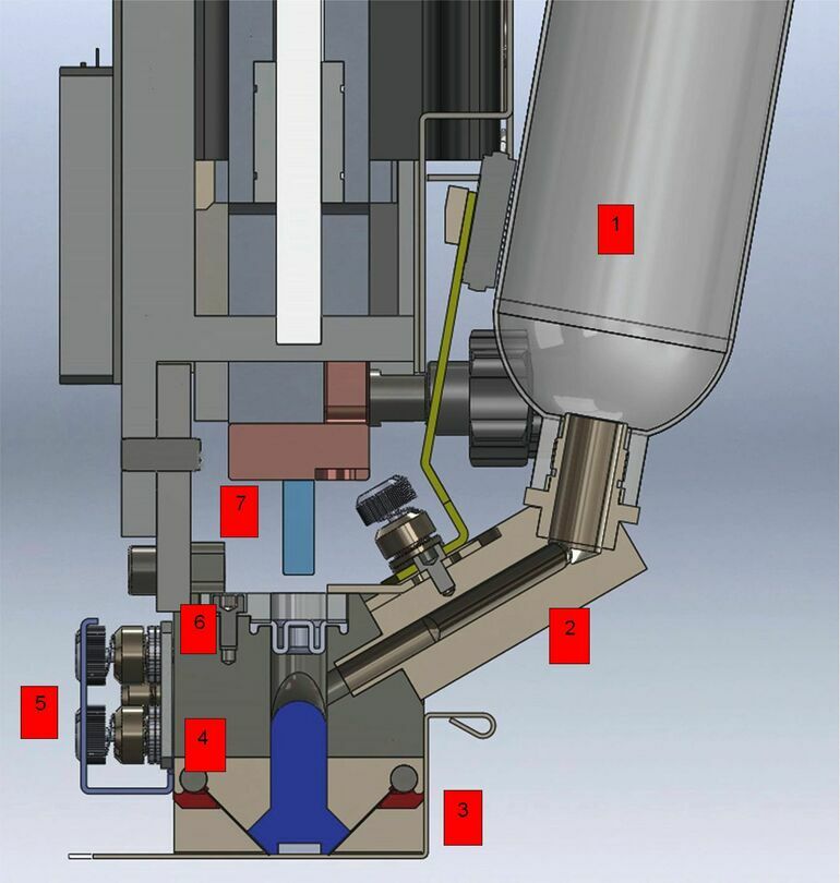
Blades were 8” (220 mm) stainless steel blades – 55-degree attack angle. The sealed chamber was a Generation 2 with an 8” (220 mm) chamber size; 3 transducers – closed looped; T/A Permalex blades ; and a paste reservoir: 2 – 6 oz (600 gram) with Semco cartridges.
Experiment design
The following is an overview of the test method used to compare standard squeegee blades to a sealed chamber:
- Print a quantity of 250 substrates in a period between 4–5 hours.
- Extract 1 substrate for Solder Paste Inspection (SPI) every 10 boards for a total of 25 data points.
- Print the other 9 substrates that are treated with mylar for cleaning purposes.
- The same stencil will be used for all tests.
- A 20-minute pause will be taken at the halfway point with the setup left in production mode.
- Wiper paper will be changed for both tests as well as paste added to maintain a 15 mm paste roll for the squeegee blade test based on need.
- Parameter settings will be made on a 5-board test prior to printing – once results are acceptable then the test will proceed.
- Once printing has commenced, no parameter changes will be made to keep the process and its steady state throughout the test.
- The order of testing will be first squeegee blades followed by the sealed chamber.
- A secondary test consisting of 50 boards and 5 data points will be performed on the Sealed Chamber after an overnight pause of a minimum of 12 hours.
Squeegee blade test
The blade length was 8” (220 mm) and the angle used was 55-degrees for best fill capability. Squeegee stroke distance increased 1” (25.4 mm) in each direction to give the paste sufficient distance for the paste to roll. Paste Height Monitor used – recommended paste roll diameter of 15 mm – limits set to 20 –10 mm. Paste was added manually as needed.
Sealed chamber test
The sealed chamber size was 8” (220 mm). Stroke distance remained at default distance at 0.5” (12.7mm).
Stencil cleaning
Wiping was performed at the completion of each print. This is to eliminate any noise from the stencil in the data. A vacuum/vacuum/dry sequence was used along with a solvent/vacuum/vacuum/dry every 5th iteration of the wipe cycle. Both wiper profiles were applied to both blades and sealed chamber.
The results of the tests (part 2) will be published in the April 2025 issue of EPP Europe.
Zusammenfassung Résumé Резюме
Mikrobauteile stellen den Druckprozess vor neue Herausforderungen. Der erste Teil des Artikels beschreibt Tests mit Einzelheiten zum Experiment, um den besten Lotpastenauftrag für Typ-6-Pulver in einer Produktionsumgebung zu ermitteln.
Les microcomposants posent de nouveaux défis au processus d’impression. La première partie de l’article décrit les tests avec les détails de l’expérience en vue de déterminer la meilleure application de pâte à braser pour les poudres de type 6 dans un environnement de production.
Микрокомпоненты дают новый вызов процессу печати. В первой части статьи описываются испытания с подробным описанием эксперимента по определению наилучшего применения паяльной пасты для порошка типа 6 в производственных условиях.


