There are some misperceptions in the implementation of a selective-soldering process in the shop floor. Despite a common believe, it is not merely bound onto the choice of a piece of equipment, and it is not just another variety of wavesoldering. Users need a thorough understanding of the process and its issues.
Gerjan Diepstraten, Vitronics Soltec
The first misunderstanding is that implementing selective soldering is mostly a matter of choosing the right machine, with the most „bells and whistles“. Not so: it’s the process more than the machine that makes the difference. Every selective-soldering procedure is unique and requires its own specific handling and soldering tools. To meet these requirements, more than just the machine is needed. The user needs a comprehensive understanding of the process, a good relationship with the supplier built on easy communication, and a logistical system with worldwide support that is able to respond very quickly to the user’s demands.
The second misperception is that selective soldering is merely wavesoldering with a few different wrinkles. However, it is very different, and the two should not be compared. Perhaps the most significant difference is that in wavesoldering, every component on a board underside is contacted by and bathed in molten flowing solder. In selective soldering, it is only specific areas. Since the board material itself is not the most efficient heat transfer medium, this benefits adjacent components and areas that we may not wish to heat to liquidus.
An example of the downside of this selective-heating area (selective soldering with nozzles) is that the outer pins of a connector, for example, will transfer more heat to the board than the inner pins, due to the fact that the colder outer area is larger, resulting in a temperature difference over the pin connector. With an optimized process we can achieve good soldering on the outer pins as well. Selective soldering requires a paradigm shift, a completely fresh approach. Moreover, this is true not only for users, but extends to the equipment manufacturer as well. A thorough understanding of the process and how the equipment fulfills the requirements is a key part of the synergy that must develop between user and equipment supplier.
The technology of selective soldering
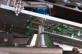
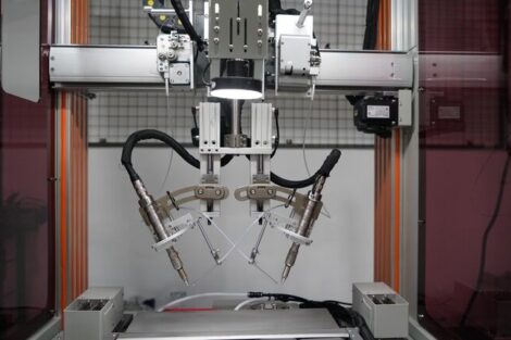
Selective soldering is the process whereby specific through-hole devices on a board are selectively soldered. Unlike to wavesoldering, where a conveyor transports boards through a stationary wave, a selective-soldering procedure uses robotics to individually move each board over stationary soldering nozzles and tooling (a solder fountain or multiple ones). The board is moved and tilted with high flexibility, precision and consistency. The robotic arm moves the assembly literally in all directions. The solder fountains are fixed in position, and the board is moved over them.
The tooling is custom to the PCB and the components, and can vary widely. While the great variety of tooling may seem to be a downside in terms of cost, tooling inventory and variability, it is also a great strength in that it gives the selective-soldering process great flexibility to meet board configuration challenges. Tooling isn’t everything. There are rules that must be observed in order to accommodate the procedure, so manufacturers and board designers must work together. Another strength is the ability to program specific recipes for each board and component. There is a wider range of programmability (individual recipes), while at the same time the entire combined recipes for a board, a series or a production shift, can be automated with the assertion that absolute repeatability and consistency will result.
Process configuration
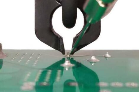
In a selective process, only through-hole components on an assembly are soldered. A key goal is to minimally affect the SMDs and other adjacent parts. Since every assembly has its specific layout and materials, the machine is designed for different configurations, with software that is very easy and product-specific to program. There are essentially two different selective-soldering procedures: dip and drag. Drag soldering is accomplished on a small single nozzle wave (what we refer to as select-wave). This soldering can reach very tight areas, individual spots or leads, and can drag-solder an individual row of leads, for example. The boards can be handled at different speeds and angles to optimize the soldering results.
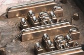
Dip soldering, conversely, involves dipping the entire assembly onto a board-specific (customized tool) nozzle plate. This we refer to as multi-wave, wherein we form all the solder joints in one operation. Though multiple connections are soldered in one stroke (as in wavesoldering), individual tooling plates for each board type are required. This is a major departure from wavesoldering.
Naturally, components for soldering must have flux applied to their leads. Again, the concept of selectivity rules: there is no need to flux any part of the board underside that is not going to be soldered. Instead, it is achieved by point-to-point fluxing. When employing a select-flux process, the fluxer is fixed, while the board travels over it. In multi-flux soldering, the board position is fixed, while the fluxer moves under the board and drop-jets pre-programmed locations.
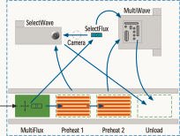
The process sequence in selective soldering is not rigidly defined and thus can be user-configured. Fluxing, preheating, dip soldering (multi-wave) and drag soldering (select-wave) is a typical sequence. However, in some cases, preheating can be eliminated or a board may only be drag soldered. Even preheat, fluxing, preheating and soldering is a possible combination. The machine can be configured to be able to accommodate many different process setups.
Other rules are needed
A key goal in selective soldering is to avoid affecting SMDs and other adjacent parts. Since every assembly is unique in its layout and parts, the soldering machine is typically designed for different requirements, with software that is product-specifically to program. However, like wavesoldering, wherein it has taken years to optimize the process, it’s also true that rules have to be created for selective soldering due to the constraints of the different process types (select, multi or both).
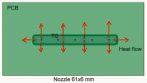
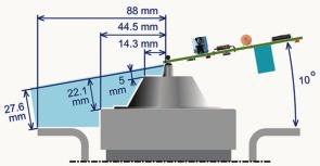
A single select-wave can be used for drag and dip soldering. For robust processing, it is recommended that the nozzle has an inside diameter of at least 6mm, when formed of stainless steel. The flow direction of the solder is defined, but can be prepared in different directions and optimized. The robot arm provides the ability to approach the wave from different directions and under different angles (between 0 and 12 degree, typically 10), giving the ability to solder many different varieties of components on an assembly.
Compared to dip soldering, the heat transfer in drag soldering is inherently better due to the motion of solder and board. The energy required to form the solder joints must be delivered by the wave and due to its low mass, the temperature of it must be relatively high to achieve acceptable process settings for the drag speed. With a setting of 275 to 300ºC, drag speeds of 10 to 25 mm/s can generally be achieved. Nitrogen is supplied to the soldering area to prevent the buildup of oxides on the wave. Drag soldering also eliminates bridges, because oxides are washed off the wave. This advantage, plus those aforementioned, contributes to the robustness and reliability of drag soldering with select-wave.
Wave height must be controlled, and for this reason, the level of solder in the pot must be measured periodically. An automatic unit keeps the solder level consistent and under control. Additionally, pump speed is controlled to keep the wave height constant. The form of the nozzle defines the flow configuration of the wave. Solder will flow the proper direction if the first pins are wetted (by a dip motion), before the dragging begins. Non-wetted pins might result in solder overflow at the backside of the nozzle. Overflow at the backside can also be caused if the immersion depth of the board is too great. This can be caused by sagging of the board, often due to the effects of high temperature. To prevent this sagging, product-specific supports can be used. Despite the benefits of select-wave drag soldering, its key drawback is extended cycle time. For this reason, dipping is used in tandem with drag soldering for specific board areas and applications. Dip soldering (multi-wave) has certain capabilities that select-wave does not. Used together, they build a robust process with minimal cycle times.
Rules for select-wave soldering
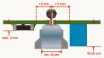
With drag soldering, lead lengths are limited due to the height of the wave. In general, lengths smaller than 2mm are preferred, but it is possible to solder up to 4mm. The minimum lead protruding length allowable depends on the board. For example, the length should be at least 1mm for single-sided boards. Recommended length should be at least 0.7mm to allow for joint inspection. A protruding lead length of more than 1mm will generally not accumulate more solder at the joint, and will therefore not add any more strength. For a robust process, the distance between the edges of the joints to surrounding components or joints that should not be soldered, must be 3mm. In the downstream direction from the select-wave, this distance needs to be greater than 4mm.
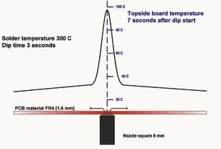
The technique employed with multi-wave nozzles is dip soldering. Although the process appears being simple (dip the board into the solder), different methods can be applied with own characteristics. During fluxing and preheating, the nozzles are covered with a glass plate, beneath which an inert-atmosphere blanket is maintained. The solder is rinsed to remove all oxides and to keep the solder in the nozzles at correct temperature. Wave height and solder temperature are critical in this process. The Vitronics Soltec selective-soldering machine is equipped with nozzles that have a patented stabilizer solder release hole that maintains all nozzles at the same temperature and solder bubble height. Stand-off supporting pins are installed to prevent PCB warpage.
A simple way to perform a dip process is putting the assembly in solder. The solder should not overflow the nozzle rim; otherwise surrounding components may come in contact with the solder. The second method is to maintain solder height just below the rim of the nozzle as the board is moved downward, until it touches the rim. Then, pump speed is increased to push the solder up and into contact with the board, afterwards, speed is reduced and the board is moved out of the solder. During this process, it is important that the pump speed not be too high during dwell, to prevent deposit of oxides. It’s also critical to ensure that the exit speed is optimized to prevent bridging.
Rules for multi-wave soldering
Nozzle dimensions in multi-wave soldering should be as large as possible to ensure a stable process, but without affecting adjacent components. This is an important and perhaps a difficult task, since the stability of the process may depend upon it. Nozzle plates are created with high accuracy, less than 0.1mm tolerance. Algorithms are used to compensate the effects of temperature. With this process, it is possible to solder joints from 0.7 to even 10mm. Shorter leads and smaller pad sizes make the process more stable and less sensitive to bridging. The space between the edges of the surrounding joints or components and the multi-wave nozzle should be >0.5mm.
Just as the process results differ from those of wavesoldering, so also do the results between select-wave and multi-wave soldering, due to the heat distribution characteristics, and the individual thermal transfer characteristics of different types of boards. Like wavesoldering, preheating is used to prepare the board; in selectivesoldering, it is used to lessen the impact of Delta-T onthe board since a localized area is in contact with the solder as opposed to the entire assembly. Still, though localized, the overall thermal effect on the PCB is much less, with a con-sequent reduction for thermal stress-induced problems.
With select-wave, ex-perimentation will determine the optimum speed through the tiny wave for, let us say, a row of leads on a board. In multi-wave soldering, dwell time is defined as the duration of contact between the molten solder and the parts. Dwell time and solderpot temperature determine the total heat flow to the soldering area. Good solder penetration in a through-hole is influenced by these parameters. Multi-wave process development will involve varying dwell times with different temperatures in order to determine optimal conditions for a specific board.
Dwell time for multi-wave application
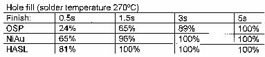
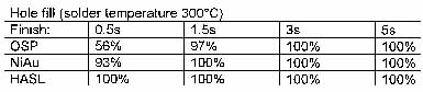
In an experiment, the optimal dwell time for a pin connector in multi-wave soldering was determined. The weight of the assembly was measured before and after soldering. The difference is the solder applied. The experiment was run at two different temperatures (270 and 300ºC) for NiAu, OSP and HASL finish. R.J. Klein Wassink (Soldering in Electronics, p 53), explains that the upper and lower fillet volume of a solder joint (for a 1.6mm board and land radius of 1.5mm) have a ratio from 1.25 to 0.69, due to differences in liquid pressure. With this information, we can calculate required hole-fill percentages. We can learn that short dwell times in dip soldering for 1.6mm boards achieve good solder filling. Another plus for short dwell times is that the flux is still stable, thus preventing bridging (see tables below).
Selective-soldering technology is robust and capable of dealing with lead-free as well as the tin-lead combinations. Its robustness and wide process window makes it ideal not only for lead-free solder-ing, where solderability and thermal vulnerability of certain components may be an issue, but also for many other coming challenges. While it differs significantly from wavesoldering, the designed-in flexibility of the equipment coupled with advanced control and automation give it extensive capability. It delivers superior quality and repeatability that cannot be achieved with hand soldering.
Rules for select-wave
Parameter settings to control:
• Solder temperature, typical 275 to 300°C
• Drag speed, typical 10 to 25mm/s
• Tilting angle, typical 10 degree
• Pump frequency, depends on nozzle
Multi-wave soldering
Parameter settings to control:
• Solder temperature, typical 275 to 300°C
• Dip speed, typical 20 to 25mm/s
• Pump frequency, depends on nozzle number
• Dip time, typically 1 to 3s.
• Speed after dip, typically 2mm/s
Zusammenfassung
Selektive Lötprozesse sind immer dann nötig, wenn man nach der Bestückung von „Exoten“ oder anderen Bauteilen kein übliches Maschinenlöten möglich ist. Hat man in kleineren Fertigungen und bei geringeren Qualitätsansprüchen noch das Handlöten favorisiert, so betrachtet man nun für hochvolumige Fertigungen bzw. große Ansprüche an reproduzierbare Qualität (unabhängig von derTagesform der Fertigungsmitarbeiter), maschinelles Selektivlöten als wesentliche Voraussetzung.
Résumé
Les processus de soudage sélectifs sont nécessaires à chaque fois qu’un soudage mécanique conventionnel est impossible après l’implantation de composants „exotiques“ ou autres. Alors que le soudage manuel était encore favorisé dans le cadre de la fabrication en faible quantité et avec des exigences qualitatives réduites, le soudage mécanique sélectif est désormais considéré comme une condition majeure pour les productions volumin-euses et lorsqu’une qualité élevée et reproductible est exigée (quelle que soit la forme momentanée du personnel de fabrication).
Sommario
I processi di saldatura selettivi sono necessari sempre quando dopo la connessione di componenti „esotici“ o altri non è possibile realizzare l’abituale saldatura a macchina. Dove finora si preferiva ancora la saldatura manuale nelle linee di produzione più piccole ed in rivendicazioni qualitative ridotte, adesso per le produzioni di volume maggiore ossia rivendicazioni di qualità riproducibile maggiori (indipendentemente dalla forma del momento degli operatori addetti alla produzione), si considera la saldatura selettiva a macchina un presupposto fondamentale.
Share:


