With increasingly dense boards, test departments are deploying more complex strategies to achieve the best coverage of potential defects. They must also meet time-to-build, time-to-market and time-to-volume business objectives and stay within restricted budgets. Manufacturing-process management (MPM) software for test can help.
Antony Caulcutt, Santiago Cabezas, Tecnomatix Unicam
Test is a vital step in the board assembly process: effective product verification ensures quality and customer satisfaction, and drastically minimizes returns or field-service activities with their related high costs. The requirement is clear: every potential defect has to be found and fixed before product shipment. But the cost of test itself can be high, and test be a bottleneck in the manufacturing lines. Outsourcing and globalization mean that the cross-functional groups that specify, design, layout, fabricate and manufacture boards are often located at different facilities. For example, the OEM may complete the initial board design or prepare design specifications, and the CEM (contract electronics manufacturer) may also take responsibility for the PCB layout design and then produce the assembly.
Visible design data and added manufacturing data
This makes collaboration between board design, layout and test groups much more challenging, because they must work together both to specify fault coverage metrics and to define and check any design modifications that are required to achieve testability. In addition, test of densely packed assemblies requires a CEM to develop complex complementary test strategies using a variety of automated optical inspection (AOI), automated X-ray inspection (AXI), in-circuit test (ICT), flying-probe test (FPT) and boundary-scan (BS) testers. After a strategy has been defined, test programs have to be generated and debugged for multiple equipment. All these tasks must be carried out before the board can go into production, and this can have a serious impact on tight manufacturing schedules, especially in volume production.
A number of tools exist to streamline the execution of these tasks. Point systems from tester vendors can help, but complementary strategies typically use testers from more than one vendor, and many of the upstream process steps for test, for example recovery of CAD and BOM (bill of material) data, are also required for assembly. In most cases, point systems involve wasteful duplication of time-consuming process steps. In-house systems that are intended to eliminate duplication are extremely costly to develop and expensive to maintain, and most leading CEMs are finding that the best solution is to use assembly and test software from an independent vendor that drives all NPI (new product introduction) processes and supports a wide range of design, assembly and test equipment. It is also a major advantage if this software is integrated with execution systems that give visibility to the faults reported by test in real-time and assist quality engineers to trace defective components and process steps, determine root causes, identify corrective actions and guide repair. By continuously monitoring and improving the manufacturing process, execution systems help to reduce downtime and improve return-on-assets. While we focus here on Unicam’s manufacturing process management (MPM) software for test and complementary test-strategy development, the software has both NPI and execution elements.
In order to collaborate effectively, cross-functional design and test groups who are jointly responsible for test strategy development need to be able to view design data and add manufacturing data anywhere. The MPM software meets this need by automatically recovering all of the board design data (layout, bill of materials and circuit schematics) needed to drive manufacturing and test processes all the way from assembly-line balancing and test strategy definition thru to the generation of machine programs and factory floor documentation. It displays the PCB layout graphically, just as the layout designer sees it on a CAD system, together with multi-page circuit schematics. It also displays the test data, including probe locations, assignments of components to different test systems, input lists and documentation. Moreover, if a board design is revised to address a testability issue, the differences between the current and previous revisions are highlighted graphically, making it easier to verify that old problems have been solved and that new ones have not been introduced.
Complementary test strategies
Given visible design and manufacturing data, a test strategy can be built based on coverage, speed and cost requirements. Developing a strategy for verifying the components on a board is much more demanding than it was in the olden days when close to 100% fault coverage could be
achieved with in-circuit bed-of-nails tests. Increasingly complex and dense boards often have circuit nets that are physically inaccessible for probing. The overall verification process for a dense board typically involves a combination of complementary steps that can include optical and X-ray inspection, boundary scan, in-circuit, functional and flying probe test. A complementary strategy needs to balance test between different systems that detect overlapping but nonetheless different defect ranges, minimizing duplicate steps for the same potential flaw, while at the same time meeting fault coverage and quality goals. Design-for-testability means that modifications to a design may be required, for example, for the addition of test points to gain access to critical nets.
Most strategies include electrical in-circuit test by a bed-of-nails or flying probe which can check for bad components and incorrect values as well as for shorts and opens. Bed-of-nails testers are faster than flying probes, but they require a pre-produced test fixture. Flying probers are typically used to verify prototypes and short production series. There are no fixture costs, and time-to-market is not held up by the additional effort of designing, manufacturing and debugging a fixture. Bed-of-nails testers are preferred for volume production because of their superior speed, and fixture costs can be spread over a much higher number of units.
There are several reasons for complementing ICT by additional test steps. First of all, denser boards and the use of ball-grid array and flip-chip components mean that physical access for probing every net is restricted, even for flying probers that can access more points than bed-of-nails testers. Secondly, the net count on some boards is very high and can exceed the number of channels available on the bed-of-nails tester. Fixture costs are a function of the number of probes (minimum one probe per net) and the probe density (means smaller and more expensive). The cost of building and maintaining a fixture for high net count, let alone the cost of using two different fixtures if the net count is greater than the tester channel count, can be prohibitive. Thirdly, certain faults are not amenable to ICT – for example solder opens on power and ground pins – but can be detected by inspection systems.
In a complementary strategy, in-circuit testers are complemented by inspection and boundary scan. Boundary-scan devices require less physical access, especially if they are interconnected. The advantage of boundary scan is that, like ICT, it exercises components electrically and can determine their functionality. On the other hand, boundary-scan devices are more expensive, and there is a trade-off between savings in test costs and increased component costs. Boundary scan in itself is slower than ICT as it is a serial bitstream. Optical inspection systems can detect gross solder problems, including solder splashes and raised pins, and check for component presence, alignment and orientation. However, optical inspection systems do require line-of-sight visibility. X-ray inspection systems do not have this limitation and can, for example, check the integrity of BGA solder joints. Board warp however causes the Z-height of the cross-section to vary, a problem not seen in optical inspection systems.
A way of a complementary test strategy is to think of the equipment forming a line, like an assembly chain, with components and defect types assigned to different systems for verification, similarly to the way in which they are assigned to paste-print, placement and oven systems. For example, if a component is assigned to a bed-of-nails or flying-probe tester, each net connected to a pin on the component will be probed by the tester. If a component is assigned to pre-solder and post-solder optical inspection, all paste dots joining the component to the board will be inspected by pre-solder inspection, and component presence/absence, orientation and alignment will then be verified by post-solder inspection, along with visible solder joints. A test coverage matrix for each component and each pin can be generated, based on component-to-tester assignments and the spectrum of faults that is covered by each system.
A first step in defining a complementary test strategy is to specify the preferred system for each part number on a board, based on coverage and speed requirements, confidence in different verification methods for different part numbers and budgetary constraints. Complications arise when physical or line-of-sight accessibility problems prevent the use of the preferred system in case of particular components. In such cases, we can either abandon the strategy, request engineering modifications to achieve design-for-testability, or specify another system.
Complementary test-strategy development tools
How can MPM software help with complementary strategy development? As mentioned, the display of design and test data (including physical layout, schematics, probe selections and library information), allows cross-functional design and test groups to use those data as well as added manufacturing data, and to collaborate effectively. For example, when bed-of-nails or flying-probe tests run into access problems, this data is needed to assess the difficulty of a problem and the options for resolving it. Also, the display of 2D component body limits and library information on device heights can help to detect potential shadow components.
Secondly, the architecture of the assembly and test software library provides an easy way of defining a complementary test strategy for a board and fine-tuning it. The library is perfectly adapted for handling cases in which we are forced to assign a component to a system which is different from the preferred tester for this part number. The same library attribute can be defined on two levels: on the part number and on the individual component, with the individual component level overriding the part number. This means that we can use the same attribute „test strategy“ to specify the preferred test system for each part number on a board and also to specify different systems for individual components belonging to the part number. For example, suppose that we are using a combination of in-circuit test and automated optical inspection and are confident that a part number can be verified by inspection. In this case, the part number will have the attribute „test strategy = AOI“. However, suppose also that one out of five components with this part number does not have line-of-sight visibility. We might want to switch the shadow component to ICT. We can do this by giving the shadow component the attribute „test strategy = ICT“ and leave the part number attribute „test strategy = AOI“ as it is. Because component attributes override part number attributes, in the search for „test strategy = AOI“ the shadow component will not be selected, but the other four parts will be.
Thirdly, the library is open and unlimited in the sense that any attribute can be added at any time. This not only makes it easier for the software to support test systems, it also means that the library can store any electrical attributes and that it is a relatively straightforward matter to interface it to other in-house and third-party libraries. Fourthly, the software includes a powerful, rule-based automatic routine for selecting probe locations on nets and reporting accessibility problems. This is critical because most strategies incorporate electrical test with its ability to check for bad and incorrect components as well as for shorts and opens. The rules are comprehensive and user-programmable, and can include priority, clearance, force and other factors and are set-up for each tester. The priority rules for a bed-of-nails tester could, for example, allow probing of thru-hole pads, surface-mount test points and vias on a net in that order. Clearance rules include the minimum distance between the body of a component and a probe so that parts are not smashed during test, together with the minimum distances between adjacent probes and between probes and board edge. Force rules push the tester to probe nets connected to all pins on a chip like an ASIC. Once the rules have been set-up (can always be fine-tuned later), automated probe-selection is run. Within minutes, the software defines locations on every net that is connected to a component earmarked for in-circuit test, and generates a board accessibility report, listing all nets that cannot be probed. If a critical pin on a component for ICT is connected to a net not being probed, it may be necessary to modify the layout in order to achieve design-for-testability.
Developing a complementary test strategy
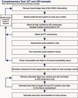
How can the software be used to define a preferred complementary test strategy and fine-tune it in the face of physical and line-of-sight accessibility issues? This can be illustrated by an example. Let’s suppose that two complementary test strategies are being developed for the same board (figure 1). Strategy 1 combines flying-probe test and optical inspection, and will be used to verify prototypes and short manufacturing runs that will get a product to the market. Strategy 2 combines ICT with optical inspection, and will be used for volume production. Since a flying prober will typically have more physical access to a board than a bed-of-nails tester, it makes sense to focus on strategy 2. If strategy 2 is viable, it should be possible to develop a practical strategy 1 by switching the components for the bed-of-nails test to the flying probe. Let’s suppose in addition that a goal of strategy 2 with the bed-of-nails test is to minimize fixture costs without compromising fault coverage. A complementary test strategy for this case can be developed as follows and is shown on the flowchart figure 1.
Entering test-strategy attributes in the library specifies the preferred verification method for each part number. Because a goal is to minimize fixture costs, all part numbers that can be automatically inspected with a high degree of confidence are assigned to the optical system by tagging them with the attribute „test strategy = AOI“. All other part numbers, including devices that require electrical verification, are assigned using „test strategy = ICT“. Then all of the inspection-assigned components have to be selected (test strategy = AOI) and checked that they have line-of-sight access. Any shadow components can be re-assigned using the component attribute ”test strategy = ICT” which overrides part number attributes. The following selection of the components with the attribute ”test strategy = ICT” will select the original components that were assigned this attribute on a part-number level in step 2, and any shadow components that were assigned this attribute on a component-level in step 3.
For the setup or check of the probe-selection rules, the automatic selection routine has to run in order to find probes on all nets that are connected to the ICT components, if this is possible in accordance with the rules. Then, the inaccessible nets in the board accessibility report must be checked. If there are inaccessible nets then (i) fine-tune the probe-selection rules to allow the use of smaller needles and re-run the routine, (ii) assign components connected to inaccessible nets to AOI, given a sufficient level of confidence and line-of-sight visibility and re-run the probe-selection routine, and/or (iii) modify the design to improve accessibility and start again at step 1.
Clicking an inaccessible net in the accessibility report automatically highlights the net graphically, and it is possible to walk around the net from node-to-node at different zoom levels and view the components that are connected. When a pin connected to an inaccessible net belongs to an ICT component, the library (provided it includes data on pin functions) or the schematic can be used to assess how important it is to test this pin electrically. In addition, the software’s graphics engine can be used to search for other components with the same part number, and the DPMO (defects per million opportunities) for the part number can be looked-up in the execution system quality module. If there is no identical component on the board or other identical parts not fully accessible, a change order can be issued. Otherwise, given a sufficient level of confidence and line-of-sight access, the component can be re-assigned to inspection, using the component attribute „test strategy = AOI“ which overrides its part-number attribute.
The next step is the generation of a component to examine the assignment report. The report generator can be configured to output a complementary statement that lists the equipment for each component, the net connected to each component pin and the probes positioned on each net. This report, coupled with data on the fault-coverage spectrum of each system, can be used to prepare a test coverage matrix for each component and each pin showing what systems will be used for verification and what potential faults are covered. For example, it may turn out that all pins on a component assigned to inspection are on nets with probes. For the elimination of duplicated tests, the component can be re-assigned to in-circuit test and the component-to-test assignment report regenerated.
The input lists for the target equipment can be automatically generated together with data required to manufacture test fixtures. For AOI, input lists will usually be generated both for pre-solder and for post-solder inspection. In addition, when ICT is used, probe locations can be selected for a single board type or a set of board variants. Then shop-floor documentation for the verification may be prepared, generated automatically and edited interactively.
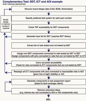
The example shown in figure 2 is simple, but a range of complementary test strategies can be developed and checked for viability in a similar way, assisted by the software. If boundary-scan test (BST) is part of the strategy, the software can extract a list of nets that are not tested by BST and select probes on these nets for in-circuit or flying probe tests. Note that there are cases in which BST checks non-BS components connected to BS components, as well as the BS components themselves wholly or partly. Any net on such a component that is not tested by BS will be probed by ICT. The strategy assumes that the boundary-scan and in-circuit testers are independent units. A simpler strategy can be used when the in-circuit tester includes BS-capability. Future concepts should see a higher degree of automation for strategy development. Both examples of complementary test strategies show how important design-for-accessibility is (part of design-for-testability), to develop a related strategy. Design-for-testability issues are identified when strategies are checked for viability.
Outlook et après test
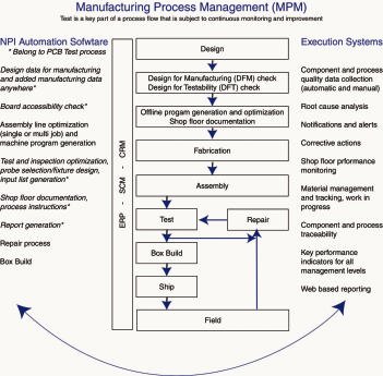
The software helps to eliminate the test bottleneck, facilitating the development of less costly strategies, and checking the viability of these strategies to identify design-for-testability issues more quickly. The ability to view design and test data anywhere makes it easier for cross-functional design and test teams to collaborate in resolving testability questions, developing test strategies and preparing fault/test coverage matrices. Once a strategy has been finalized, the software speeds up the generation of documentation and input lists for the equipment, together with the generation of fixture-manufacture data. The software can also be used for assembly and NPI applications, so that the same family of tools is used across a board (figure 3).
Quality engineers, plant supervisors and managers want to have visibility to the faults reported by real-time tests and to receive alerts if the defects exceed specified limits. Quality assurance requires determining whether the faults are caused by real defects, and this has to be drilled down to the root causes, so that corrective actions can be taken. If a defect has been introduced during manufacturing (for example an open solder joint), the particular process step necessitates that it be identified and corrected to prevent recurrence. In the case of a component defect, all boards with the same part need to be traced so that it can be determined whether it’s a common defect, or it only affects a particular batch of components or is an isolated case. If repair is economically justified, boards with defects are transferred to a rework loop. The repair operator needs a presentation of board graphics with the pinpointed defect locations, together with historical data documenting rework actions in the past. After these actions have been taken and logged, repaired boards must be re-introduced into the process for re-test. All of these downstream processes and more can be managed by the manufacturing process management (MPM) software and its NPI and execution systems modules.
While there are several methods to check process design and implementation, the wider range of applications, greater integration and level of maintenance provided by independent NPI and executions-systems software merit consideration in comparison with point solutions from equipment vendors and in-house solutions. More manufacturing process management value can be achieved by a more comprehensive solution that eliminates duplication, developed and supported in response to the requirements of the global manufacturing industry.
ZUSAMMENFASSUNG
Test und Inspektion in der Baugruppenfertigung wird oft als „notwendiges Übel“ betrachtet, das erhebliche Kosten verursacht. Aber es ist evident, daß ohne die Kontrolle von Prozeß, Bauteilen und Schaltungsfunktionen keinerlei Aussagen über Qualität und Zuverlässigkeit eines Produkts möglich sind. Dabei steigen mit höheren Schaltungsdichten und der Verwendung von Bauteilen in Advanced-Packages die Anforderungen fortlaufend. Mit Manufacturing-Process Management Software kann man sowohl die Kosten in den Griff bekommen, Doubletten bei Prüfschritten vermeiden als auch sämtliche Erfordernisse an Manufacturabilty, Testability oder der Zeitspanne bis zur Markteinführung und Volumenfertigung erfüllen
RÉSUMÉ
Les tests et les révisions dans la production de modules sont souvent considérés comme „un mal nécessaire“ qui génère des coûts élevés. Mais il est évident que sans le contrôle des processus, des pièces et des fonctionnements de circuits, il est impossible de se prononcer sur la qualité et la fiabilité d’un produit. Plus les circuits se multiplient et plus on utilise de pièces en logiciels de pointe, plus les sollicitations augmentent en permanence. Avec le logiciel de gestion de processus de fabrication, il est possible de maîtriser les coûts, d’éviter la répétition d’étapes de vérification et de se conformer aux exigences imposées par la faisabilité de fabrication et de vérification ou par la période jusqu’au lancement sur le marché et à la production en volume.
SOMMARIO
I test e le ispezioni nella produzione di gruppi costruttivi molto spesso vengono considerati un „male necessario“, che causa notevoli costi. Ma è evidente il fatto che senza opportuni controlli del processo, dei componenti costruttivi e delle funzioni di collegamento non sono possibili alcune determinazioni della qualità e dell’affidabilità di un prodotto. Il risultato di ciò sono aspettative continuamente crescenti con maggiori densità di collegamento e nell’impiego di componenti costruttivi in Advanced-Packages. Con il Manufacturing-Process Management Software si possono controllare sia i costi che prevenire doppiette nei passi di controllo come pure corrispondere alle varie rivendicazioni ed aspettative poste ai fattori di Manufacturabilty, Testability o al lasso di tempo fino all’introduzione sul mercato e alla produzione di grandi volumi.
Share:


