
From 1987 onwards, VXI was king, offering a modular approach to automated testing based on VMEbus. Unfortunately though, because VMEbus is not part of modern computer architecture, VXI is not able to take complete advantage of the advances in PC technology and therefore cannot reap the tremendous benefits of mainstream software, lower costs and high performance that PXI offers. The growth of PXI since its introduction in 1998 has been phenomenal, and its uptake currently shows no signs of a slowdown.
Traditionally, VXI has addressed the needs of high-end automated test applications and has been very successful in military-aerospace test applications, offering high channel count applications in engineering test. PXI (PCI eXtensions for Instrumentation) defines a compact modular based platform for test, measurement and control applications. Based on the industry standard PCI (Peripheral Component Interconnect) bus, it inherently brings the benefits of mainstream PC computing power and flexibility to a much wider audience. With the added benefits of reduced costs and programming time, PXI has been more widely adapted in commercial ATE, design verification and simulation applications.
When designing functional test applications based around PXI, a structured approach must be taken when considering how to connect the unit under test (UUT) to the test system. For small systems with less than 50 testpoints or only a few instruments, it may be sufficient to simply cable from the instrument to a breakout box or screw terminals and connect to the UUT. For larger systems with hundreds of testpoints, multiple instruments, reconfigurable system requirements, or frequent connects/disconnects, a more comprehensive approach to planning connections is required. In order to handle this level of signal connections, a mass interconnect system is the best solution.
The basic principles of mass interconnect
A mass interconnect system is a mechanical arrangement designed to easily facilitate the connection of a large number of signals either coming from or going to a UUT. For automated test systems, this usually entails some mechanical enclosure through which all signals are routed from instruments (typically in a rack) to the UUT, making it easy to quickly change out UUTs or to protect the cable connections on the front of the instruments from repeated connect/disconnect cycles. There are several major components of a mass interconnect system:
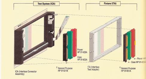
- Receiver The receiver (or interface connector assembly) is the mechanical device that provides the connection to and from the test equipment. The re- ceiver can be configured to utilize a combination of signal, power, coax, triax, pneumatic and vacuum connections depending on the specific test requirements. The receiver houses the specific modules and contacts that relate to the test system and the instruments used within it. The receiver provides the mechanical alignment and forces required to provide a consistently reliable connection.
- Mounting hardware Mounting hardware holds the receiver onto the front of the rack or alternatively onto a standard chassis. In many instances the mounting plate is hinged to allow access to the instruments and cabling behind the receiver.
- Interface Test Adapter (ITA) The ITA is the main mechanical mate to the receiver. It is the “UUT side” interface that houses the modules/cables that will interface to the connections on the UUT. In many test systems, one receiver system can be connected to several different ITAs, each ITA having a different enclosure, cables, and UUT attached to it for rapid changeover of a test system requirements. The ITA houses the modules and contacts that relate to the specific UUT.
Why use a mass interconnect system?
Mass interconnect systems are most often required in the following circumstances:
- Frequent UUT changeover If a test system has been designed to handle the requirements of multiple UUTs (each having different connection requirements), there is no quicker way to change the signal connections than with a mass interconnect system. Whether the UUT requires a small or large number of connections, a mass interconnect system can usually make all of those connections from one ITA to another in a matter of seconds with a simple lever. Many manufacturing test platforms are designed using a standard set of instruments and full-crosspoint matrix switching so that any instrument can be connected to any testpoint, allowing just about any UUT to be connected to the equipment set. All of the custom wiring is done in the ITA enclosure to accommodate the specific requirements of the UUT, and many different UUTs could be used with the same instrument set.
- Intense mating cycle requirements All interface connectors (small or large density) have a recommended maximum mating lifetime. For many standard connectors on commercially available PXI instruments, this might be 500 to 1000 cycles before signal integrity can no longer be guaranteed. For RF connectors such as SMAs or SMBs, the number is much smaller, and the effect of a damaged connector can be crippling to a high-frequency instrument. In this way, a mass interconnect can preserve the life of test equipment by providing an interface with many thousands (often >20,000) of rated connections. The connection on the instrument side is only made once – from the instrument to the receiver module – while the UUT can be frequently connected or disconnected through the ITA-receiver mate. Even if the receiver modules experience pin failure or compromised signal integrity which is still far less expensive to replace in most cases than the instrument itself.
Which style of mass interconnect system is best?
Once a decision has been made that the mass interconnect route is best, a number of possible receiver styles are available:
- Fixed receiver In the simplest configuration the receiver fixes directly to a fixed mounting plate with the receiver modules being wired back to the PXI instruments. Accessibility to the rear of the re- ceiver is extremely difficult, making maintenance and alterations extremely time consuming.
- Hinge down receiver This improves on the fixed set up by attaching the receiver to a hinged mounting plate that allows the receiver and connected modules to rotate down, thus allowing access to the wiring and instrumentation behind the system. To facilitate this, additional cable length between the instrument and receiver is required.
- Reverse mount hinge down receiver This evolution in mass interconnection allows the receiver to be hinged down while leaving the wiring in place. This is achieved by mounting the modules to the rear of the receiver and releasing them individually before rotating the receiver body out of the way. To reconnect the modules into the receiver, the unit is rotated back to vertical and the modules simply click back into place. The advantages of this type of arrangement are in the reduced length of wiring leading to improved signal clarity coupled with a significant improvement in accessibility to all internal areas of the system. Indeed, in some arrangements, the receiver can be hinged down and removed completely while leaving all the wired modules in position, still attached to the test system.
- Scout direct access receiver system Scout is the newest advancement in mass interconnect technology for PXI based ATE. The 21-slot interface fits in standard 19” racks and adapts to standard PXI chassis. Each instrument is attached to a connector module via a DAK (direct access kit). Electrical connection between the instrument and the interface module is accomplished using PC boards and flex circuits thus providing a wireless PXI interconnect solution. Among the numerous advantages offered by this type of approach are:
- The replacement of wiring harnesses with dedicated wireless assemblies
- The ability to perform signal monitoring directly off the PCB
- Enhanced MTBF (mean time between failure) via the removal of hard wiring
- Guard traces for enhanced noise reduction
- Solid assembly from the backplane through to the mass interconnect
- Dramatically reduced build time
- Greatly improved reliability of connection
The steady move towards PXI based test systems and the accompanying development of new support in terms of both hardware and software is providing increased possibilities on an almost daily basis. To take best advantage of this, the role of a good interconnection solution must not be undervalued. Choosing to use a mass interconnect solution is the first decision. Choosing the best mass interconnect solution follows right behind.
EPP Europe 452
Share:


