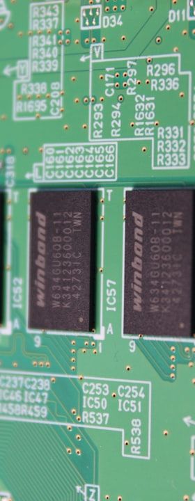
The continuing proliferation of mixed-technology printed circuit boards — carrying both surface-mount devices and through-hole components — has made selective soldering one of the most strategically important processes in electronics manufacturing. Where wave soldering exposes an entire board underside to a solder bath, selective soldering applies molten solder only to defined locations, protecting heat-sensitive SMT components already soldered on the bottom side. The result is a tightly controlled, programmable process that demands a precise understanding of flux chemistry, thermal management and solder hydrodynamics.
Selective soldering systems are broadly divided into two architectural families: miniwave nozzle systems, which direct a small, continuously pumped solder fountain against individual joints or connector rows, and laser-based systems, which use focused infrared or diode-laser energy as the heat source with wire solder feed. Miniwave systems currently dominate industrial practice and form the basis of the following discussion.
System architecture and the role of the solder nozzle
The core of a miniwave selective soldering machine is the solder pot and nozzle assembly. Solder is maintained at a stable temperature — typically between 260 °C and 300 °C depending on alloy — and pumped through a titanium or stainless-steel nozzle whose diameter is matched to the target geometry, ranging from around 4 mm for single connectors up to custom-shaped wide nozzles for multi-row headers. The upward-flowing solder column wets the board pad and pin while the board is moved across the nozzle in a programmed X-Y trajectory.
Nozzle geometry directly influences joint quality. A symmetric, laminar solder flow creates stable wetting conditions, whereas turbulence causes oxidation, solder splashing and bridging. The stand-off distance between nozzle tip and board underside — commonly referred to as the immersion depth — must be optimised: too shallow and the solder column collapses before wetting the hole barrel; too deep and solder creeps laterally, threatening adjacent components. Most modern systems allow immersion depth to be set independently per joint in the soldering programme.
Flux application: chemistry, deposition methods and process windows
Flux is applied prior to soldering to remove surface oxides from pads and pin surfaces and to maintain a solderable surface throughout the thermal cycle. In selective soldering, flux is deposited only onto the areas to be soldered, using either a drop-jet fluxer — which operates on inkjet principles and achieves spot diameters down to approximately 2 mm — or a spray fluxer with a miniaturised nozzle. Drop-jet fluxing offers superior positional accuracy and avoids flux contamination of adjacent SMT joints or connectors, making it the preferred choice on high-density boards.
The flux chemistry must be matched to the alloy, the base material and the required post-process cleanliness. No-clean fluxes based on organic acids and rosin derivatives are widely used; however, the residues they leave behind must be electrically benign and must not interfere with in-circuit testing probes. Where higher flux activity is needed — for example with difficult-to-solder alloys or oxidised pin finishes — water-soluble fluxes may be selected, but these then mandate an aqueous cleaning step. The flux solid content, typically expressed as a weight percentage, determines residue volume and activation intensity; values between 2 % and 10 % are common in selective soldering applications.
Flux volume per deposit is a critical process parameter. Insufficient flux leads to poor hole-fill and dewetting; excess flux produces splatter during preheat and can cause voiding if flux volatiles are trapped in the joint. Process qualification should include flux volume measurement via weight or optical methods as part of the statistical process control plan.
Preheat: balancing thermal mass and flux activation
After fluxing, the board passes through a preheat zone before reaching the solder nozzle. Preheat serves two functions: it activates the flux by driving off carrier solvents and initiating the chemical reduction of oxides, and it reduces the thermal shock imposed on the board and components when they contact the solder. Inadequate preheat results in flux spatter, cold joints and, on thick multilayer boards, poor barrel fill because the solder freezes before flowing fully through the plated-through hole.
Preheat is typically accomplished by infrared emitters, convection heaters or a combination of both. Board topside temperatures at the point of solder contact should generally reach 100 °C to 130 °C for no-clean flux systems; lead-free alloys with higher liquidus temperatures — SnAgCu at approximately 217 °C — demand more aggressive preheat profiles than tin-lead. The thermal gradient across a densely populated mixed-technology board must be characterised with thermocouple profiling during process development, since tall connectors and heat-sinking copper planes create localised cold spots that compromise solder flow.
Solder alloy selection and dross management
The choice of solder alloy affects not only joint reliability but also process stability over time. Tin-silver-copper (SAC305) is the dominant lead-free alloy in selective soldering, offering a good balance of wetting behaviour, mechanical strength and availability. However, SAC alloys are more aggressive toward iron-containing nozzle materials than tin-lead eutectic, leading to iron leaching and nozzle erosion. Titanium-coated or ceramic nozzles extend service life; regular inspection of nozzle geometry is recommended as part of preventive maintenance.
Dross — the oxide layer that forms on the solder surface — is an inherent by-product of high-temperature solder exposure to atmosphere. In miniwave systems, the continuous pumping action mechanically breaks up and incorporates dross, which can then transfer to joints as inclusions. Nitrogen inerting of the solder pot and nozzle environment reduces oxidation rates significantly, typically lowering dross formation by 50 % to 80 % compared with air atmospheres, improving wetting and reducing nozzle maintenance frequency. Regular solder analysis for copper and other contaminants from board surface finishes is advisable; copper content above approximately 0.3 % by weight degrades wetting noticeably.
Programme development, quality metrics and defect diagnosis
A selective soldering programme defines, for each joint or joint group, the nozzle path, travel speed, immersion depth, dwell time and solder contact length. These parameters interact: increasing travel speed reduces heat input and may cause cold joints; decreasing speed risks overheating thermally sensitive components mounted close to the solder point. The process window — the combination of parameters delivering acceptable results — must be experimentally determined and then held under statistical process control.
The primary quality criterion for through-hole selective solder joints is hole fill, defined in IPC-A-610 as the minimum percentage of the barrel height filled with solder — typically 75 % for Class 2 assemblies. Automated X-ray inspection is the most reliable method for measuring hole fill non-destructively, since the three-dimensional solder distribution inside the barrel is not visible from the board surface. Automated optical inspection can detect surface-visible defects such as bridges, insufficient solder fillets and missing joints, but must be regarded as complementary rather than a substitute for X-ray on through-hole connections.
Common defects in selective soldering include bridging between adjacent pins, icicles, insufficient fillet formation and blow-holes caused by outgassing of moisture from the board or via fill material. Root-cause diagnosis requires systematic variation of individual process parameters combined with cross-section analysis of suspect joints. Maintaining a detailed process log — including solder pot temperature trends, nozzle condition and dross removal records — enables correlation of process drift with quality excursions before they propagate to production yield loss.
Integration into the SMT line and outlook
Selective soldering machines are positioned after SMT reflow and before final inspection in the line sequence. Effective integration requires coordination with upstream and downstream equipment on board handling, pallet or fixture design and traceability data. Pallets must be dimensionally stable at soldering temperature, must not outgas into the flux zone and must provide adequate clearance around solder targets. Fiducial recognition by the selective soldering system ensures that mechanical tolerances in pallet loading do not translate into joint positional errors.
Looking ahead, the increasing density of through-hole connectors on power electronics and automotive boards, combined with the push toward higher-reliability alloy systems containing bismuth or indium additions, will continue to challenge flux chemistry and thermal management. Closed-loop process control — where inline measurement of flux deposit volume and joint temperature feeds back directly to the soldering programme — is gaining traction as manufacturers seek to reduce first-pass defect rates without expanding inspection resource. Mastery of the fundamental process variables described here remains the indispensable foundation for any such advanced automation strategy.