However, it is a less-known fact that current lead-free soldering temperatures can also cause a shift in the properties of some components, which can then impact the functionality of sensitive electronic circuits, like e.g. measuring devices. These kind of failures are often harder to determine.
An easy way to solve problems related to higher soldering temperatures is to use a soldering alloy that has a lower melting point. However, these alloys can have limitations in mechanical strength. Shock and vibration resistance tend to be the weakest points, which limits the field of use. The LMPA-Q low melting point alloy has been specifically developed, by Interflux Electronics N.V., to overcome these limitations.
The following case study investigates the suitability of the LMPA-Q alloy with the use of Megger Instruments Ltd.‘s handheld high accuracy measuring device. Currently, the device is being used with a SnAg3Cu0,5 alloy, it is sensitive to heat in the soldering process, and is shock resistant in the field.
Assembly of the electronic unit
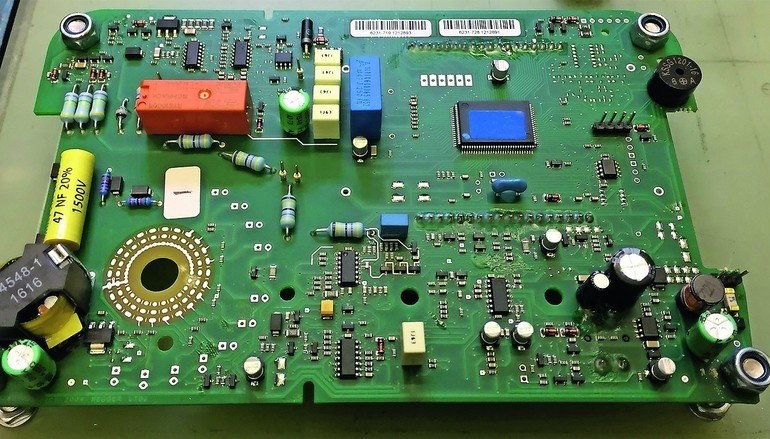
The electronic unit consists of a double sided I-Ag finished PCB board with SMD and through-hole components. The temperature sensitivity mainly lies in the different capacitors on the board that are all somehow affected by heat. The boards are printed with the DP 5600 LMPA-Q solder paste with ROL0 classification. The units are reflow soldered in a full convection oven without nitrogen and with a profile of a peak temperature below 205 ºC. This reflow profile will indulge the Tº-sensitive components. The through-hole components are being soldered with LMPA-Q solder wire.
Vibration and shock resistance testing
Handheld devices need to have good shock resistance in the field. In the past, this particular property has proven to be the weak point of traditional low melting point alloys. The electronic unit is submitted to vibration and shock resistance testing according to the test standards described in BS EN 60945 and BS EN 60068. For objectivity purposes, the test are performed by a third party specialized testing lab.
The Half Sine shock test will perform shocks in both directions on all three axes. Shocks will last 11 ms with a peak acceleration of 30 G or defined by practical limitations of the test setup. In this case, the shock in the X-axis was limited to 10 G due to the breaking of the measuring sensor with higher peak accelerations. Shocks in Y and Z-Axis were at 30 G. As a reference, 10G is equal to 4 times the shock a mobile phone experiences when it is dropped 1 meter above a concrete floor.
The vibration test will start with a resonance frequency search on the electronic device on all 3 axes. The resonance frequency for a device is when it reaches the highest force. This will be different for each device, as well as, for each axis. Once the resonance frequency is found, a 2H vibration endurance test with a peak acceleration of 3G will be performed. If the resonance frequency isn’t found, a standardized endurance frequency of 30 Hz will be used with a peak acceleration of 3G. In this case, a resonance frequency was only found for the X-axis at 82,92 HZ.
Results and extended testing
After the shock and vibration resistance testing, the units soldered with the LMPA-Q alloy were subject to visual inspection. None of the units showed signs of failures or misalignments. The units from the company were all subject to ICT and functional testing, and they all passed.
From the results, it was concluded that the alloy has sufficient mechanical strength for handheld devices. However, to get a better idea of how it holds up against the SnAg3Cu0,5 alloy, comparative vibration endurance tests were also done.
Comparative shock is more difficult to test due to the previously mentioned limitations of the test setup. Shock and vibration resistance tend to go hand in hand, as vibration is a fast sequence of shocks.
The same handheld high accuracy measuring device was chosen for this test. Electronic units soldered with SnAg3Cu0,5 and LMPA-Q were provided to the test lab. Since vibration in the X-axis was expected to be more critical, it was chosen as the only axis for this test. A standard test frequency of 30 Hz in combination with a peak acceleration of 18 G was used initially for a 30 minute vibration endurance. After visual inspection, the acceleration or frequency was increased step by step, until a first failure was noticed. The first failure manifested itself on an electronic unit soldered with the SnAg3Cu0,5 alloy at a frequency of 50 Hz and a peak acceleration of 25 G.
Results and conclusion
As the LMPA-Q alloy passed the required shock and vibration tests and the SnAg3Cu0,5 alloy failed in comparative vibration testing, the LMPA-Q alloy was found suitable for the production of Megger’s handheld high accuracy measuring device. This alloy allows for lower soldering temperatures in the soldering processes and temperature sensitive components are less affected by heat. Based upon these results, the company has started the procedure to homologate this alloy for more processes and products.
productronica, Booth A4.281
Zusammenfassung Résumé Резюме
Es ist eine bekannte Tatsache, dass Temperaturen beim bleifreien Lötprozess temperaturempfindliche Bauteile und sogar Leiterplattenmaterialien beschädigen können. Dabei befindet sich auf nahezu jeder Baugruppe eine kritische Komponente wie beispielsweise BGAs, Sicherungen, Displays, LEDs, Spulen und Transformatoren oder Displays. In den meisten Fällen kann solch Beschädigung durch visuelle, optische, Röntgeninspektion, ICT oder Funktionstests erkannt werden.
Il est bien connu que les températures pendant la soudure sans plomb peuvent abîmer des pièces qui sont sensibles à la température et aussi les matériaux d’une carte de circuit imprimé. Des éléments critique, tel que les BGA, les fusibles, les écrans, les LED, les bobines, les transformateurs, se trouvent sur presque tous les modules. Dans la plupart des cas, ces dégâts peuvent être détectes par des tests visuels, optiques, aux rayons X, aux TIC ou test de fonctionnement.
Общеизвестно, что высокая температура в процессе бессвинцовой пайки может повредить как компоненты, чувствительные к нагреву, так и материал печатной платы. При этом на почти каждом электронном узле найдутся критически важные компоненты, например, BGA, предохранители, дисплеи, светодиоды, катушки и трансформаторы. В большинстве случаев повреждение таких компонентов можно выявить при помощи визуально-оптического, рентгенографического контроля, сравнительных испытаний при приемочном контроле или в ходе проверки работоспособности.