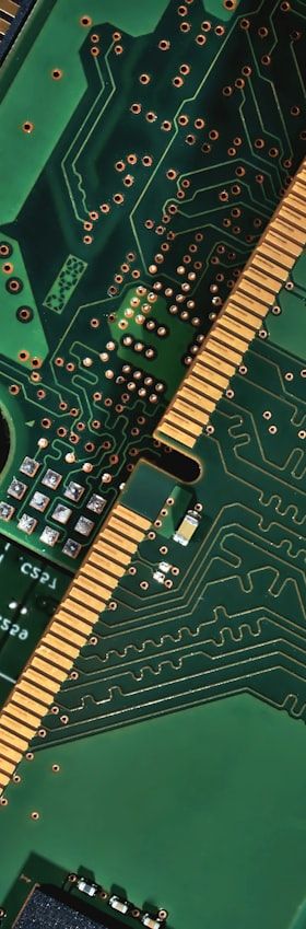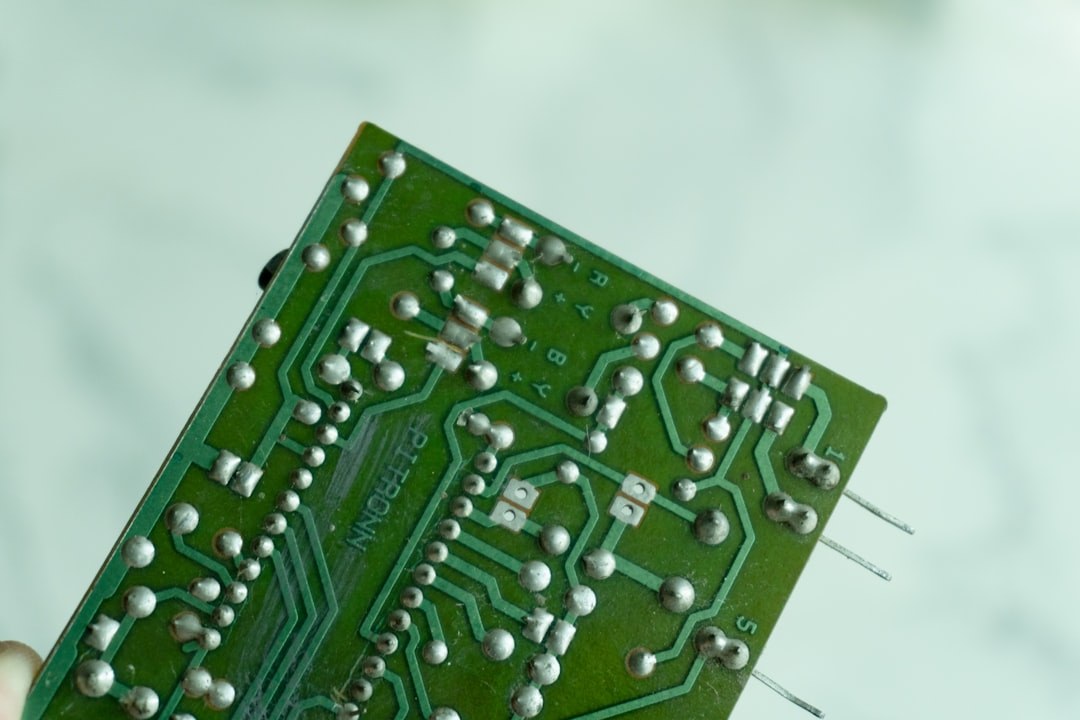
Wave soldering once dominated through-hole assembly, but the proliferation of mixed-technology printed circuit boards — carrying both SMT components on the bottom side and leaded through-hole parts — has rendered blanket wave exposure increasingly problematic. Heat-sensitive connectors, electrolytic capacitors and fine-pitch leaded devices cannot always tolerate full immersion in a solder wave, and masking fixtures add cost and process variability. Selective soldering addresses this challenge by delivering molten solder precisely to defined through-hole locations while leaving adjacent components and areas entirely unaffected.
The technology is not new — selective soldering systems appeared in volume production environments during the late 1990s — yet its relevance has grown steadily as board complexity increases and lead-free alloys demand tighter thermal control. A clear understanding of process fundamentals, equipment architectures and quality-assurance measures allows process engineers to extract maximum value from selective soldering without compromising joint reliability.
Core Process Sequence: Flux, Preheat and Solder
Every selective soldering cycle consists of three sequential sub-processes: fluxing, preheating and soldering. Fluxing is applied by a drop-jet or spray nozzle that deposits a defined volume of liquid flux onto each pad-and-lead combination. Drop-jet systems offer precise, programmable placement with minimal overspray, while mini-wave spray heads cover larger areas more rapidly. The choice of flux chemistry — typically no-clean low-residue formulations or water-soluble variants — must be matched to the subsequent cleaning strategy and the electrical requirements of the end product.
Preheating follows immediately after fluxing. Its purpose is threefold: activating the flux to remove surface oxides, reducing thermal shock to the board and components, and bringing the assembly to a temperature from which the solder contact can achieve sufficient hole-fill without dwelling excessively. Infrared panel heaters, forced-convection heaters or a combination of both are used. Bottom-side preheat temperatures in the range of 100 °C to 130 °C are common for standard FR-4 substrates, though thick, thermally massive boards may require higher setpoints. Inadequate preheat is one of the most frequent root causes of poor hole-fill and solder balling.
Equipment Architectures: Point Nozzle versus Mini-Wave
Commercial selective soldering systems fall into two broad architectural categories. Point-nozzle systems — sometimes called laser-selective or single-nozzle systems — use a small-diameter nozzle, typically 4 mm to 10 mm, through which molten solder pumps upward to form a controlled fountain. The board, held in a transport frame, moves over the nozzle under CNC control, following a programmed path that visits each target joint in sequence. This approach delivers the highest spatial selectivity and is well suited to densely populated boards with isolated through-hole positions scattered among surface-mount components.
Mini-wave systems use wider nozzles or nozzle arrays shaped to match a group of through-hole positions simultaneously — for example, an entire connector footprint. Because multiple joints are wetted in a single dip or drag cycle, throughput is significantly higher than with a point nozzle. The trade-off is reduced flexibility: changing the nozzle geometry requires tooling changes, and the spatial separation between adjacent solder targets must be sufficient to prevent bridging.
A third variant, the dual-bath system, equips a single machine with both a point nozzle and one or more mini-wave modules, allowing a process engineer to assign each joint population to the most appropriate soldering method within a single automated pass. This architecture is particularly attractive in high-mix, medium-volume environments where different board types share the same production line.
Solder Alloy Selection and Pot Management
The transition from tin-lead to lead-free alloys under RoHS legislation has had a pronounced impact on selective soldering. SAC alloys (Sn-Ag-Cu, most commonly SAC305 with 3 % silver and 0.5 % copper) are widely adopted, but their higher liquidus temperature of approximately 217 °C compared with 183 °C for eutectic Sn63Pb37 demands elevated pot temperatures, typically 260 °C to 280 °C. This narrows the process window and increases the thermal load on components during dwell.
Copper dissolution from board pads and component leads is an important metallurgical concern: at elevated temperatures and extended dwell times, copper from the wetted surfaces leaches into the solder pot, gradually raising the copper content and changing the alloy's flow characteristics. Most equipment manufacturers recommend monitoring dissolved copper levels via periodic ICP analysis and establishing a defined top-up and pot-refresh protocol. Low-silver alloys such as SN100C (Sn-Cu-Ni-Ge) are an alternative that reduces raw material cost while offering acceptable joint quality for many application classes, though wetting speed is generally slower than SAC305.
Programming, Optimisation and Process Parameters
Selective soldering programs are generated from CAD/CAM data, with each solder point defined by its X-Y coordinate, nozzle diameter, solder contact time (dwell), travel speed across the nozzle and, where applicable, the drag direction. Dwell time is the most influential single parameter for hole-fill quality: insufficient dwell leaves voids or incomplete fill; excessive dwell risks component thermal damage or leaching of component termination metallisation.
Optimisation follows a design-of-experiments approach, varying dwell time and preheat temperature systematically while measuring hole-fill percentage by cross-sectioning or X-ray inspection. IPC-A-610 specifies a minimum 75 % vertical hole-fill for Class 2 assemblies and 100 % for Class 3, providing quantitative acceptance criteria. Nozzle wetting angle, solder flow rate (controlled by pump speed) and nitrogen inerting of the solder pot are secondary parameters that fine-tune the process once the primary window is established.
Inspection and Quality Assurance
Post-process inspection of selective solder joints relies on a combination of automated optical inspection (AOI) for surface-visible defects such as bridges, insufficient solder and solder balls, and 2-D or 3-D X-ray inspection for hole-fill verification. AOI cameras with angled views can image the top-side fillet and the board underside simultaneously on dual-camera systems, flagging the most common defect modes within seconds per board. X-ray is typically applied on a sampling basis or during initial process qualification rather than at 100 % in-line inspection, owing to throughput constraints.
Statistical process control (SPC) charting of key process parameters — pot temperature, preheat temperature, flux volume per drop and dwell time — provides the early-warning capability needed to detect drift before it propagates into yield loss. Coupling SPC data with MES traceability links each board's soldering parameters to its serialised identity, enabling root-cause analysis if field failures emerge and supporting audit requirements in regulated industries such as automotive and medical electronics.
Practical Considerations and Outlook
Selective soldering is not universally applicable: it is most cost-effective when through-hole populations are moderate in density and spatially well separated. Very high through-hole counts may still favour wave soldering with selective masking, while extremely isolated single-pin locations on thermally simple boards can sometimes be addressed by robotic soldering irons. The decision requires a rigorous analysis of joint counts, board topology, alloy requirements and cycle-time targets.
Looking ahead, the integration of selective soldering systems into closed-loop smart factory architectures is advancing steadily. Inline solder volume measurement, real-time nitrogen consumption monitoring and AI-assisted defect classification are being incorporated into current-generation platforms. As board complexity continues to increase and mixed-technology assemblies remain a fixture of industrial, automotive and medical electronics, selective soldering will retain its role as an indispensable process technology — provided that its fundamental parameters are understood, controlled and continuously monitored.