
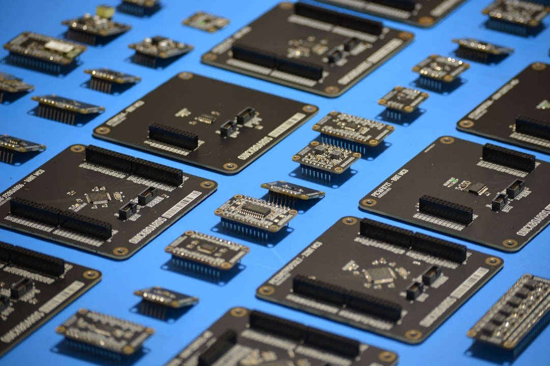
Modern printed circuit board assemblies rarely consist of surface-mount components alone. Connectors, transformers, electrolytic capacitors and other through-hole parts continue to be specified by designers for mechanical, electrical or thermal reasons. Where these components coexist with SMT devices on the same board, the classical wave soldering process creates a conflict: the solder bath would damage already-reflowed SMT components on the bottom side, while masking and pallets add cost and complexity. Selective soldering resolves this conflict by applying liquid solder exclusively to predefined through-hole joints, leaving the surrounding assembly untouched.
The technology has matured significantly over the past two decades and today encompasses several distinct machine architectures, each with characteristic process windows, throughput profiles and cost structures. Choosing the right approach requires a clear understanding of the underlying physics as well as the production environment in which the process must operate.
The Three Principal Machine Architectures
Selective soldering equipment is generally grouped into three categories: laser soldering systems, miniature-wave (point-to-point) systems and drag-soldering systems. Laser soldering applies a focused beam to heat the joint and melt pre-deposited solder wire or perform contact-free soldering; it is used primarily for heat-sensitive or extremely fine-pitch applications and is not the dominant platform for high-volume through-hole work.
Miniature-wave systems are the most widely deployed concept. A small solder nozzle — typically between 4 mm and 25 mm in diameter — creates a stable, upward-flowing wave of liquid solder. The board is positioned above the nozzle by a servo-controlled XY axis, and each joint or small group of joints is wetted sequentially. Nozzle geometry, solder flow rate and dwell time are programmable per joint, enabling precise adaptation to component-specific requirements. Drag soldering extends this concept by moving the board over a larger nozzle or a nozzle row to process a linear sequence of joints in a single pass, trading flexibility for higher throughput on regularly spaced patterns.
Flux Application: The Critical First Step
Before the solder nozzle contacts any joint, flux must be applied to the target area. In selective soldering, fluxing is performed by a dedicated module — either a drop-jet fluxer or a mini-wave flux applicator — immediately preceding the solder station. Drop-jet fluxers operate on the same principle as inkjet printing: a piezoelectric actuator ejects a controlled droplet volume, typically between 1 nl and 20 nl per drop, onto each pad. This approach offers high spatial resolution and avoids flux contamination of adjacent SMT components or connectors.
Flux selection is equally important. No-clean flux formulations with low solid content are preferred in most production environments because they eliminate a cleaning step, but their residues must be electrically safe and cosmetically acceptable. ROL0 and ROL1 classifications according to IPC J-STD-004 describe rosin-based, low-halide fluxes that are widely used in selective soldering. Where cleaning is part of the process, water-soluble ORL0 or ORL1 fluxes can be chosen for superior activating power. The flux quantity must be sufficient to ensure complete pad and barrel coverage yet small enough to avoid blooming or migration under adjacent components.
Preheating and Thermal Management
Selective soldering introduces localised thermal stress into a board that has already undergone one or more reflow cycles. A preheating stage between flux application and soldering is therefore essential. Preheating activates the flux, reduces the thermal delta between board and solder nozzle, minimises thermal shock to the substrate and lowers the risk of cold joints caused by heat extraction through the PCB mass.
Top-side infrared panels, bottom-side convection heaters or a combination of both are used to bring the board to a preheat temperature typically in the range of 100 °C to 130 °C, measured at the board surface. For assemblies with large copper planes or multi-layer constructions with high thermal mass, extended preheat zones or reduced conveyor speed are necessary. Thermal profiling with thermocouple arrays across representative board positions is best practice before releasing a new product to production.
Solder Materials and Alloy Considerations
The transition to lead-free manufacturing under the RoHS directive has significant implications for selective soldering. SAC alloys — most commonly SAC305 (Sn96.5Ag3.0Cu0.5) — are the standard in lead-free selective soldering. Their liquidus temperature of approximately 217 °C demands higher nozzle temperatures than traditional SnPb eutectic, typically 270 °C to 310 °C depending on board mass and nozzle diameter. At these temperatures, dross formation and solder oxidation in the nozzle reservoir are accelerated, making nitrogen inerting a practical necessity rather than an option.
Nitrogen blanketing, applied both to the solder reservoir and locally around the nozzle tip, reduces oxide formation, improves wetting and extends solder bath life. Residual oxygen content at the nozzle is typically maintained below 20 ppm in well-engineered systems. Solder bar quality — including silver and copper content tolerances as well as contamination limits for bismuth, aluminium and other tramp elements per J-STD-006 — must be monitored regularly through chemical analysis to prevent gradual alloy degradation in the bath.
Process Qualification, Joint Quality and Inspection
Joint quality in selective soldering is assessed against IPC-A-610 Class 2 or Class 3 criteria depending on the end-use application. Key indicators include barrel fill (minimum 75 % for Class 2), fillet geometry on both primary and secondary side, absence of bridging, icicles, cold joints and disturbed joints. Because the process applies solder sequentially to individual joints, any variation in nozzle temperature, flow rate or dwell time affects only the joints processed under those conditions — making parameter logging and traceability per joint technically feasible and increasingly demanded by automotive and medical customers.
Automated optical inspection after selective soldering can detect most surface-visible defects, but solder fill within the barrel is not visible from the top side. X-ray inspection remains the definitive method for verifying barrel fill, particularly for multi-row connectors or dense through-hole clusters. Integrating automatic X-ray inspection into the post-selective-soldering workflow is therefore recommended for high-reliability assemblies, while statistical sampling may be acceptable for less critical products once the process is well characterised.
Practical Considerations and Outlook
Programming a selective soldering system requires accurate CAD data for component positions and an understanding of the mechanical interference envelope around each joint. Nozzle diameter must be chosen so that the solder wave contacts the target pads without touching adjacent SMT components or sensitive connector housings. For congested layouts, miniature nozzles below 6 mm in diameter extend process capability but reduce thermal mass delivery and may require increased dwell time to achieve full barrel penetration on thick multilayer boards.
Process stability over time depends on disciplined maintenance: regular solder analysis, dross removal, nozzle cleaning and flux system calibration. Statistical process control applied to measurable parameters such as nozzle temperature, flow rate and cycle time per joint allows early detection of drift before it manifests as solder defects. As mixed-technology boards continue to proliferate — driven by the persistent necessity of mechanically robust through-hole interconnects alongside high-density SMT — selective soldering will remain a core competence in electronics manufacturing, and mastery of its fundamentals will be a consistent differentiator between average and high-performing production operations.