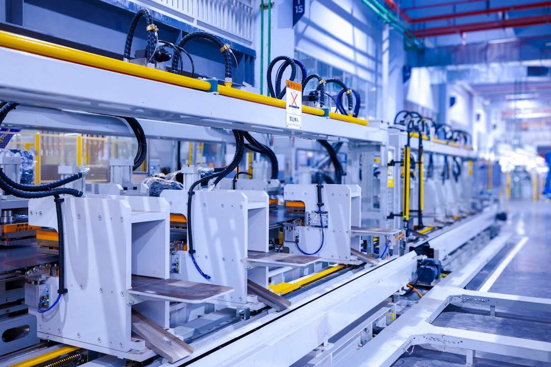
In surface mount technology, the placement of components onto solder-pasted PCBs is the process step that most directly determines throughput, flexibility and assembly quality in a production line. Pick-and-place machines — also referred to as component placement systems or mounters — carry out this task at speeds ranging from a few thousand to well over 100,000 components per hour, handling everything from large connectors and odd-form parts down to 01005 passives and fine-pitch BGAs. The enormous range of component types, board layouts and production volumes encountered in electronics manufacturing has led to a correspondingly diverse landscape of machine architectures, each with distinct trade-offs between speed, accuracy and flexibility.
For process engineers and equipment planners, understanding the fundamental principles behind these machines — how they move, how they recognise components, how they achieve and verify placement accuracy — is a prerequisite for making sound decisions in machine selection, line balancing and process optimisation.
Kinematic Concepts: Gantry, Rotary and Multi-Beam Architectures
The dominant kinematic concept in modern high-speed placement is the gantry architecture, in which one or more beam structures carry placement heads across the board in a Cartesian X-Y coordinate system. Single-beam machines with one movable head are straightforward and cost-effective for lower-volume or high-mix applications. Dual-beam and multi-beam configurations allow simultaneous pick-and-place cycles on different sections of the board, significantly increasing effective throughput without proportionally increasing footprint.
An alternative approach is the rotary or turret head, in which a rotating carousel carries multiple nozzles. While the carousel spins continuously — picking components at one station and placing them at another — individual nozzles cycle through vision inspection and correction in between. This architecture can achieve very high placement rates for small passive components but is generally less flexible when handling large or unusual parts. Many contemporary machines combine both principles, pairing high-speed rotary heads for passives with flexible multi-nozzle gantry heads for ICs and connectors, allowing the machine to be optimised across the full bill of materials.
Feeder Systems and Component Supply
Reliable component supply is a prerequisite for uninterrupted placement. The vast majority of SMT components arrive on tape-and-reel, and tape feeders — in 8 mm, 12 mm, 16 mm and wider formats depending on component size — are the standard feeding method. Modern intelligent feeders communicate with the machine controller to confirm tape advancement, detect empty reels and enable splicing without stopping the line. For tray-packaged ICs, waffle-pack or JEDEC-tray feeders present components in an array format; the machine picks sequentially or uses specialised tray-change mechanisms to maintain throughput.
Vibration feeders and bulk feeders handle certain component types, though their use in high-precision SMT assembly is limited. The growing adoption of intelligent feeder management systems — where each feeder slot is tracked via barcode or RFID and cross-referenced with the assembly program — directly supports traceability requirements in IPC-CFX and MES-integrated production environments. Incorrect feeder setup remains one of the most frequent sources of wrong-component placements, making automated verification at the feeder level a standard countermeasure in quality-critical production.
Vision Systems and Component Recognition
Accurate placement depends on knowing the precise position and orientation of each component as it is held by the nozzle, as well as the exact fiducial reference points on the PCB. Modern pick-and-place machines use upward-looking cameras (bottom vision) to inspect the component while it is in transit from feeder to board. This on-the-fly inspection measures X and Y offsets and rotational deviation from the nozzle centre, allowing the machine to correct placement coordinates in real time without an additional stop-and-inspect cycle.
Board fiducial recognition uses downward-looking cameras mounted on the placement head or on a dedicated camera beam. Global fiducials establish the overall board coordinate system, compensating for board stretch, warpage and positioning tolerances in the conveyor system. Local fiducials — placed near fine-pitch or BGA pads — provide additional correction for high-accuracy placements. For transparent or low-contrast fiducials, lighting geometry and camera wavelength selection are critical parameters. Laser height sensors are increasingly integrated to measure component and board height, enabling nozzle touchdown control that prevents component damage and solder paste smearing during placement.
Placement Accuracy: Specifications, Measurement and Practical Limits
Placement accuracy is typically specified as a statistical value at a defined confidence level — commonly ±X µm at 3σ (three sigma, covering 99.73 % of placements). Manufacturers distinguish between repeatability (the machine's ability to return to the same position consistently) and accuracy (the absolute positional correctness relative to the nominal coordinate). In practice, the total placement error budget includes mechanical tolerances of the gantry, thermal expansion of machine structures, nozzle wear, vision system resolution and board fixturing quality.
For 0402 and 0201 passives, placement accuracies in the range of ±50 µm to ±75 µm at 3σ are typically sufficient. Fine-pitch QFPs with 0.5 mm lead pitch and BGAs with 0.4 mm ball pitch demand better than ±30 µm to ±40 µm at 3σ, and advanced packaging formats such as chip-scale packages or flip-chip components may require sub-20 µm capability on specialised high-accuracy machines. It is important to note that published machine specifications are derived under controlled laboratory conditions; real-world accuracy must be verified through process capability studies on the actual board type and component mix.
Nozzles, Force Control and Handling Sensitive Components
Nozzles are the direct interface between machine and component. Standard nozzles rely on vacuum generated by the machine's internal pump; the nozzle shape and orifice diameter are matched to component size and body geometry. Nozzle material — typically carbon fibre composites, stainless steel or engineering plastics — is selected to avoid ESD damage and minimise wear. For components susceptible to mechanical stress, such as MLCC capacitors of larger case sizes or ceramic oscillators, controlled placement force (Z-axis force control or compliant nozzle mechanisms) is essential to prevent cracking.
Odd-form components that cannot be reliably gripped by vacuum — through-hole parts, connectors with complex geometries, shielding cans — are handled with mechanical gripper attachments. These require additional teach-in of pick and place sequences and are typically processed at lower speeds. The integration of odd-form placement capability within standard SMT machines reduces the need for manual insertion steps and supports fully automated assembly lines.
Line Integration, Program Management and Process Stability
Pick-and-place machines do not operate in isolation. In a modern SMT line, they receive board transport from the upstream stencil printer and pass assembled boards to the reflow oven, all under conveyor width and speed synchronisation. Machine programs — containing component coordinates, nozzle assignments, feeder slots, vision parameters and placement sequences — are generated from CAD data and bill-of-materials files, ideally through offline programming systems to minimise changeover time. Line balancing software distributes the component list across multiple placement machines to equalise cycle time and maximise overall line throughput.
Statistical process control at the placement stage — monitoring offset trends per component type, nozzle or feeder slot — allows process engineers to detect drift before it results in defects. Integration with MES platforms via IPC-CFX or SMEMA protocols enables real-time data collection on placement counts, error events and feeder status, feeding the traceability records that are increasingly mandated in automotive, medical and aerospace production. Regular machine calibration, nozzle inspection and feeder maintenance schedules are the operational foundation on which placement process stability ultimately rests.