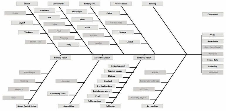
Influences in the assembly production on the formation of solder joints and thus on their quality are affected by an unmanageable number of parameters that are increasingly difficult to control or master. There are a variety of factors that can provide an initial insight into the complexity of the problem. However, only two factors can be used immediately before production of the assemblies in question to prevent voids from forming.
Factors influencing voids
The first factor is the stencil and the design of the aperture, the second is using vacuum technology in the soldering process itself. A unique selling point is that vacuum soldering can even be used in the production process, as a “firefighter” when there is short-term increase in the occurrence of bubbles. It reacts flexibly to fluctuations in the supply quality of components, printed circuit board surfaces or batch fluctuations in solder pastes.
Where large numbers of voids or void size have been created in the first soldering pass using a conventional soldering system, both assemblies and series production items can be repaired in Rehm Thermal Systems’ modern vacuum soldering systems, such as the VisionXP+ Vac convection soldering system or the vapour phase soldering systems from the CondensoX series. These would normally have to be marked as rejects because they contravene relevant IEC standards criteria or IPC guidelines.
Vacuum with reflow
What does vacuum actually mean, though, and how does it influence the design of a reflow soldering system?
Vacuum is defined in DIN 28400 as follows: “Vacuum means the state of a gas when the pressure of the gas and thus the particle number density inside a container is lower than outside or when the pressure of the gas is lower than 300 mbar, i.e. lower than the lowest atmospheric pressure existing on the earth’s surface.”
The assembly profiling is the same as in vacuum-less processes, only here the vacuum process can be applied between the peak and cooling zone. This vacuum process does not have to be a single step but can also be split into several holding steps for more sensitive components. In the same way as a surfacing scuba diver, the pres-sure can escape gradually from the components and solder joints. Similarly, the speed needed to create a vacuum can be influenced to adjust the dynamics to prevent effects such as solder splashes and the like. One of the main advantages of convection soldering machines in today’s production process is the high production throughput.
A compromise has to be found here between the quality that needs to be achieved (void content in the solder joint) and the cycle time. As a rule of thumb: the lower the void fraction needs to be, the higher the extra cycle time to the standard vacuumless profile. For example, a cycle time of 25 seconds can be achieved without vacuum equipment for a 200 mm-long assembly. If a 100 mbar vacuum process is selected here to achieve a void ratio below 10 % for QFN components, this can add 9 seconds to the above cycle time.
The cycle times can also be changed in both directions, however, depending on whether the tolerance needs to be tightened to 5 % or broadened to 20 %. A second thought about the really needed void ratio percentage pays off in both ways, quality wise and cost wise!
Comparison of soldering methods
The influence of the different soldering methods on void creation was examined using a reflow convection soldering and a reflow vapour phase soldering machine. This comparison shows that vapour phase vacuum soldering and convection vacuum soldering do not differ. The advantages can therefore be used in convection soldering in the same way, but when making comparisons the “marginal parameters”, such as the solder paste, which differ regarding suitability for the different soldering methods, must never be forgotten.
This influence is also seen when using two SAC solder pastes, but with different soldering flux formulations. There are larger void formation deviations in the QFN component between convection soldering with air and vapour phase soldering. The vapour phase soldering process here, however, is inert, even without the use of nitrogen. This itself can have a significant influence when using a soldering flux. The beauty of the vacuum option is that the influence of paste can be drastically minimised, irrespective of the soldering method used.
Rehm’s convection soldering system ensures optimum heat transfer
Soldering field study
A comparison was made here between these two soldering methods and different template apertures to evaluate the respective influencing variables. The stencils were also varied in material thickness and manufacturing method. A template with a 120 µm thickness was produced without any additional “refinement steps”. Its counterpart was built with a plasma-coated and electropolished surface and a template thickness of 110 µm. The test boards ran equally divided in numeric terms with both template variants.
In an extreme comparison of soldering at ambient pressure, compared with vacuum at 10 mbar, there were clear differences shown between vacuum application and standard reflow system. Throughput with reduced vacuum at 100 mbar verifies the result and shows that even with less effort, a result below 2 % voiding is achieved for the component combination. This has a significant influence on the cycle time, since during unthrottled vacuum pump operation, the necessary process times from 1000 mbar to 100 mbar are the same as from 100 mbar to 10 mbar (or 10 mbar to 1 mbar). This means that it is necessary to always work with only as much “pressure” as needed.
The influence of the selected aperture geometries only shows significant differences without the use of vacuum, mainly in the number of gas bubbles formed and partly on the total void ratio.
The subjective impression is that the plasma template tends to result in a little less voiding, which can be attributed to the better release of the paste and the associated more stable printing process. A stable and constant paste pressure supports the soldering process here.
Standard deviation of process
Finally, a consideration of the process stability during soldering: the target figures for voiding are always absolute figures, such as 15 % or 5 %. Attention is rarely paid to the standard deviation of the process, although this is significant for the success of these specifications. The void content without vacuum was examined, where a standard deviation of 5.75 % and an average value of 19 % was achieved. A limit of 40 % can be safely complied with this approach; any requirement below this must inevitably lead to rejects.
However, since new components and printed circuit boards contain new input parameters when they are delivered, the result for the average value and the standard deviation can shift in one direction or the other at any time, without any opportunity for the process owner to intervene at the production line.
The same component with vacuum support not only achieves absolute maximum void values 5 %, which is already less than the standard deviation of the previous process, but the standard deviation is drastically reduced too. This leads to more stable processes and results on the production line.
Summary
Convection soldering with targeted vacuum use can contribute to a significant reduction in the number of voids and void content. Despite the extra processes, a high throughput and thus short cycle times can still be achieved. Two major benefits of the vacuum convection soldering machine are on the one hand the possibility to “react” to quality fluctuations in components, pastes and PCBs and on the other hand the “reduction” of the standard deviation of void formation in the soldering process.
Helmut Öttl, Head of Application and Process Development, Rehm Thermal Systems GmbH
Das Vakuumlöten hat sich seit Jahrzehnten in Kontaktwärme- und Dampfphasenlötsystemen bewährt und reduziert erheblich Voids in Lötverbindungen. Doch welche Bedeutung hat dies für das Konvektionslöten, die heute am häufigsten verwendete Löttechnik für höchsten Durchsatz?
Depuis plusieurs décennies, le brasage sous vide a fait ses preuves dans les systèmes de brasage par chaleur de contact et en phase vapeur et il limite considérablement les voids au niveau des joints de soudure. Mais quelles en sont les implications pour le brasage par convection, qui est aujourd’hui la technique la plus utilisée pour les cadences élevées?
Вакуумная пайка зарекомендовала себя на протяжении десятилетий в системах контактной термопайки и конденсационной пайки, позволяя значительно сократить количество пустот в паяных соединениях. Но какое значение это имеет для конвекционной пайки, наиболее часто используемой на сегодняшний день технологии, обеспечивающей наибольшую производительность?