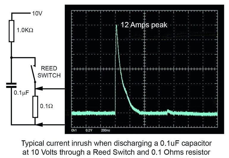
High current or high power inrushes are the most damaging and most frequent causes of contact damage when using reed relays. They have a specific maximum amount of current, voltage, and power ratings. The power figure is the product of the voltage across the open contacts before closure and the instantaneous current that is made.
Contact abuse
At Pickering, we have lost count the number of times we have heard something along the lines of: “I was only switching to 5 volts at 50 milliamps on this CMOS logic board”, as the user usually disregards the current inrush into the sprinkling of decoupling capacitors and several microfarads of reservoir capacitance on that board.
However, only relying on electronic current to limit the power supplies to protect relay contacts should not be done. Limiting electronic current takes a finite time to react and there are often decoupling capacitors on the output of a power supply. There is nothing better than limiting resistive current.
Due to the charging of capacitive loads, inrushes also discharges capacitors, which can become a problem as the current is often only limited by the resistance of the reed switch and PC tracks. Even capacitors charged with low voltages can cause current inrushes of tens of amps and although they may only be for microseconds, they can cause damage to small reed switches.
As voltage increases for some applications, inrushes can become an even greater issue, specifically when discharging cables after the proof testing of high voltage. The energy stored in a capacitance is equal to ½ CV2 joules, meaning it increases with the square of voltage. So when increasing from 10 volts to 1000 volts, the stored energy will increase by 10,000 times.
If you have had a relay contact stick closed, to be free only with a slight tap, or had a longer than expected release time, it is most likely caused by a micro-weld due to a current inrush.
‘Hot’ versus ‘cold’ switching
Reed relays generally have a higher carry current rating compared to their ‘hot’ switching current rating. It is usually during ‘hot’ switching where contact damage occurs, due to the resulting arc across the contacts as they open or close. A severe current overload will quickly melt the contact area causing the two surfaces to fuse together, creating a hard weld as soon as the contact closes. Less severe current inrushes will cause a milder weld or gradually build up a ‘pip’ on one contact and erode a ‘crater’ on the other, depending on the direction of current flow. These can eventually lock together. Arcs can occur when contacts open, particularly when the load is inductive. Back EMFs from inductive loads should always be limited, usually by a simple diode for DC loads or by a snubber or varistor for AC loads.
One way to reduce or remove these issues is to use the ‘cold’ switch. This is a common technique in test instrumentation, where the current or voltage stimulus is not applied to the switch until after the relay has been operated and the contact bounce is finished. In the same way, the stimulus is removed before the contact is opened. By using this technique, there won’t be any arcing or switched current inrushes and the relay will achieve maximum life, often into billions of operations.
When calculating the delay time between switching on the relay coil and applying the current to the switch, it is important to consider the effects of high ambient temperature, as this is likely to be encountered. The maximum operating time and bounce figures given on the data sheets are at a 25 °C ambient level. At higher temperatures, the resistance of the coil winding will increase at a rate of 0.4 % per °C, this being the coefficient of resistance of the copper coil wire. There will therefore be a corresponding fall in coil current and the level of the magnetic field that is generated to operate the reed switch. This lower drive level will increase the operating time slightly. The timing figures on Pickering data sheets are normally quite conservative, so this is unlikely to be an issue for the normal ambient specification of 85 °C. However, it is also necessary to consider any additional self-heating within the relay, due to a high carry current and the witch resistance (I-Squared-R Watts), and to allow a little more time before turning on the current through the switch.
productronica, Booth A1.452
Zusammenfassung Résumé Резюме
Graham Dale, Direktor für Forschung und Entwicklung bei Pickering Electronics, erläutert das Thema von Reed Relais, dass mit zunehmender Last und heißem Schalten an den Kontakten höhere Temperaturen entstehen, die das Kontaktmaterial verschleißen. Der Artikel soll den Nutzern von Reed Relais Tipps geben, um deren Zuverlässigkeit zu erhöhen.
Graham Dale, le directeur de la Recherche et du Développement de Pickering Electronics, explique le thème des relais reed qui, avec l’augmentation de la charge et une commutation à chaud au niveau des contacts, crée des températures plus élevées qui épuisent le matériau de contact. L‘article fournit des conseils aux utilisateurs de relais reed pour augmenter leur fiabilité.
Грэхэм Дейл, директор по НИОКР в компании Pickering Electronics, затрагивает тему герконовых реле, а также износа материалов контактов в результате возрастания нагрузки и срабатывания из горячего состояния. Статья содержит советы по повышению надежности герконовых реле.