In surface mount assembly, reflow soldering is the process step that transforms a precisely printed and populated PCB into a mechanically and electrically functional assembly. Despite its apparent simplicity — a board travels through a controlled thermal environment and emerges with completed solder joints — the underlying physics involve a complex interplay of heat transfer, flux chemistry, alloy metallurgy and component geometry. Mastery of each variable is a prerequisite for consistent, high-yield production.
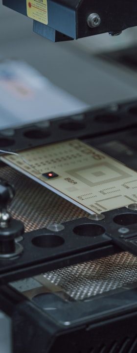
Reflow ovens today are convection-dominated systems, typically featuring between five and twelve independently controlled heating zones plus a cooling section. Forced convection with nitrogen or air as the heat transfer medium is the industry standard. Vapour-phase reflow, which uses the condensation heat of a fluorinated fluid, occupies a smaller but significant niche, particularly for assemblies requiring very uniform heating or containing heat-sensitive substrates. Both approaches pursue the same objective: guiding every solder joint through a defined time-temperature profile without overheating components, delaminating laminates or leaving flux residues that compromise reliability.
The Four Zones of a Reflow Profile
A standard reflow profile is conventionally divided into four regions: preheat, soak (also called thermal equalisation), reflow and cooling. During preheat, the board rises from ambient to a soak temperature — typically 150 °C to 180 °C for lead-free Sn-Ag-Cu (SAC) alloys — at a ramp rate generally not exceeding 3 °C per second to avoid thermal shock to ceramic capacitors and other sensitive passives.
The soak zone serves two functions: it allows the entire board, including thermally massive connectors and fine-pitch QFPs or BGAs, to reach a uniform temperature before liquidus, and it activates the flux to remove oxides from pad and ball surfaces. Soak duration typically ranges from 60 to 120 seconds. An excessively long soak can exhaust flux activity prematurely, while too short a soak leaves thermal gradients that cause tombstoning or head-in-pillow defects in area-array packages.
The reflow zone itself — the period above liquidus (TAL, time above liquidus) — is where the alloy melts, wets the metallised surfaces and forms the intermetallic compound (IMC) layer that constitutes the actual metallurgical bond. For SAC305, the eutectic-like liquidus is approximately 217 °C; peak temperatures in production typically fall between 235 °C and 250 °C. TAL is commonly targeted at 30 to 90 seconds: too short risks incomplete wetting and voiding; too long promotes excessive IMC growth and component degradation. Controlled cooling at 3 °C to 6 °C per second solidifies the joint with an acceptable grain structure and residual stress level.
Alloy Selection and Its Process Implications
The transition from tin-lead (Sn63/Pb37, liquidus 183 °C) to lead-free alloys driven by RoHS legislation fundamentally altered profile requirements. The roughly 34 °C increase in liquidus for SAC alloys narrowed the process window — the gap between peak temperature and the damage threshold of components and substrates became significantly smaller. Low-silver SAC alloys such as SAC105 or SAC0307 reduce material cost and improve thermal fatigue resistance in some applications but require attention to their wider pasty range and potentially higher void content.
Bismuth-containing alloys such as Sn-Bi and ternary Sn-Ag-Bi variants are gaining traction in low-temperature reflow applications, with liquidus temperatures as low as 138 °C for the Sn58Bi eutectic. They offer energy savings and compatibility with temperature-sensitive substrates including paper-based boards and some flexible circuits. The critical engineering constraint is bismuth's embrittlement effect when mixed with lead contamination from legacy components, demanding strict supply-chain control.
Nitrogen Atmosphere and Void Reduction
Reflow in a nitrogen atmosphere — typically with residual oxygen below 100 ppm — reduces oxidation of molten solder and pad surfaces, improving wetting and reducing the minimum flux activity required. The practical benefit is most pronounced for low-residue or no-clean flux systems and for assemblies with fine-pitch components or OSP-finished boards, where oxide build-up during the profile is particularly detrimental.
Voiding within solder joints, especially beneath thermal pads of QFNs and under BGA balls, is a persistent challenge. Voids originate from flux outgassing that cannot escape before the solder solidifies. Countermeasures include optimising aperture design for thermal pads (using segmented or cross-hatched stencil apertures to provide outgassing channels), adjusting the soak profile to allow earlier flux burn-off, and using vacuum-assisted reflow ovens that apply a controlled pressure reduction during the liquid phase to actively extract gas bubbles. Acceptable void limits are defined by standards such as IPC-7093 and IPC-A-610, with functional and reliability thresholds depending on application class.
Common Reflow Defects and Root Causes
Tombstoning — the standing-up of a chip component on one termination — results from an imbalance of surface tension forces as one pad wets and reflows before the other. Root causes include asymmetric thermal mass, misregistered paste deposits or non-simultaneous pad wetting. Solder balling arises from flux splatter or solder paste slump during preheat, leaving isolated solder spheres on the board surface. Head-in-pillow (HiP) in BGA assemblies occurs when the ball and the printed paste deposit each melt but fail to coalesce due to an oxide skin or insufficient flux activity, a defect particularly associated with warped packages and inadequate soak profiles.
Non-wetting and dewetting indicate insufficient flux activity or contaminated surfaces, often traceable to expired paste, improper storage or substrate surface finish degradation. Graping — a cluster of small, incompletely coalesced solder spheres — is characteristic of Type 4 or finer powder solder pastes where oxidation of the high surface-area powder is not adequately controlled by flux. Each of these defect signatures has a traceable process root cause, which underlines the value of coupling reflow process data with downstream AOI and X-ray inspection results.
Thermal Profiling: Measurement and Optimisation in Practice
Establishing and validating a reflow profile requires thermocouple profiling of a representative production board with thermocouples attached at defined critical locations: the slowest-to-heat thermal mass (e.g., a large connector body or a ground-connected pad) and the most thermally vulnerable component (e.g., a small 0201 resistor adjacent to a copper pour). The profile is iteratively adjusted by modifying zone temperatures, conveyor speed and fan speed until all monitored locations satisfy the alloy and component specifications simultaneously.
Modern thermal profiling systems can acquire continuous temperature curves and automatically calculate process capability indices against user-defined specification limits for each profile segment. This quantitative approach replaces trial-and-error and provides documented evidence for process validation under IPC-7711/7721 and automotive quality frameworks such as IATF 16949. Periodic re-profiling is recommended whenever board design, component population or solder paste specification changes, since each variable affects the thermal mass distribution and therefore the optimum oven recipe.
Outlook: Inline Process Control and Adaptive Reflow
The integration of reflow ovens into MES environments is increasingly standard in high-reliability and automotive assembly. Real-time logging of zone temperatures, conveyor speed, nitrogen consumption and board throughput provides the traceability records demanded by end customers and enables statistical process control. Emerging concepts in adaptive reflow use pyrometer arrays or thermographic imaging within the oven to infer board temperature in real time and adjust zone setpoints dynamically, compensating for load variations without operator intervention.
As assembly complexity grows — driven by higher power densities, mixed alloy assemblies and the introduction of embedded components — the reflow process window will continue to narrow. A thorough understanding of the underlying thermal, chemical and metallurgical principles remains the most reliable foundation for engineers tasked with maintaining yield, reliability and throughput in modern SMT production.