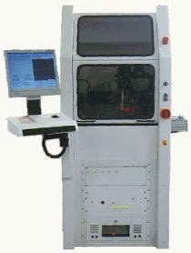
It’s a widely accepted experience that multiple different factors can disturb a continuous dispensing-process procedure. In this dispenser DJ 335 (figure 1), changing flow characteristics and viscosity of dispense materials are compensated by a product heating station and the use of a volumetric dispense valve. The positioning accuracy of the dispense needle is an even more critical factor. Here, we will briefly show the capabilities of the newly developed dispenser for operations in difficult-to-handle underfill processes.
For an underfill process, the dispense needle has to evenly and precisely follow the chip edge in a proximate distance. There are the main parameters needle height, distance of the needle to the chip edge along the dispense track and the volume flow of the material. They have to be controlled in a way that the entire flip-chip component will be underfilled, and no excess material can migrate to the surface of the chip.
As shown in figure 2, a low-viscosity liquid is dispensed on the substrate, next to a mounted and soldered flip chip. The capillary effect lets the liquid flow under the chip into the gap formed with the substrate, until the entire component area is fully covered. The flow behavior of the material and the chip size define the dispense method (see figure 3 for three different procedures).
The one-side-dispensing procedure can be used for underfilling of small chips. For larger components, the dispensing step from one side needs to be repeated after the previous deposit has been absorbed. The two-side-dispensing method can cause air bubbles under the chip which are typically not allowed. The precise positioning of the material track is the main requirement for an even flow timing and thus the utilization of the entire system which defines its productivity. This is valid for all three methods shown.
If a typical distance between flip chip and substrate is around 40 to 60µm (1.6 to 2.4 mil), it can be expected that the required needle-placement tolerance relative to the chip position is smaller than 15µm (0,6 mil), and the required height accuracy relative to the substrate surface is below 10µm (0.4 mil). See figure 4 for the wetting angle.
In case of the one-side-multiple dispensing (figure 3), the exact placement of the dispensed tracks defines the flow speed of the material. A methodically calculated and fixed timing between the deposition of sequenced dispense tracks requires the previous supplied material track to have undergone the flow process, before dispensing of a following track is possible.
For the exact placement of the needle tip, it is necessary to exactly recognize the contour of the mounted flip chip. The dispenser includes a high-resolution pattern recognition system to guarantee precise chip detection. Two independently programmable light sources with vertical light through the camera lens and a diffuse ring light with exchangeable light-color capability offer optimal illumination, which is necessary for exact pattern recognition. Even tilted chips can be determines with this system.