Gerjan Diepstraten, Vitronics Soltec
Increasing soldering temperature for Pb-frees narrows process windows, making the procedure less robust unless monitored properly. It is also necessary to review materials. Components or flux may not be compatible with higher temperature treatment, and might need to be replaced with others that comply. In general, this obviously results in higher costs for material/components process and energy.
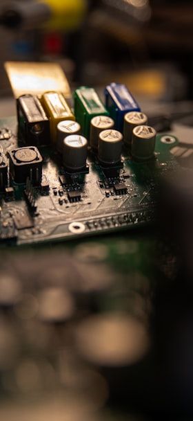
Apart from lead-free process implementation, there is the ongoing trend towards miniaturization. SMT was introduced, and in turn through-hole components were widely replaced. Reflow soldering was introduced, and component dimensions were reduced dramatically. Nevertheless, the reflow process is not fully capable of replacing wave sol-dering. Assemblies will still contain through-hole parts such as connec-tors, electrolytic capacitors and other bulky components that are not compatible with reflow soldering. Due to this fact, we recognize that methods are shifting. Reflow processes are combining with through-hole soldering, which is now shifting from hand and selective-wave operation in pallets to selective-soldering machines. These systems are specially designed to meet the needs of through-hole components in an advanced way with reliable and dedicated methods and tools.
The goal of lead-free reflow soldering is that there be no net change to footprint, line-speed and throughput as a result of this shift. The definition of the lead-free reflow process window is currently the topic of debate within companies, consortia and projects. Maximum temperature definitions are of interest for the materials used. These temperatures might be at approximately 245 or even up to 260ºC for some applications. These are upper limits, so the definition will end up with 245ºC/±5K. Since these temperatures are relative close to the melting point, the lead-free reflow process will be a focus for reducing DELTAt. Factors that affect the temperature difference delta include the following: conveyor speed, temperature profile and heat transfer. For next-generation ovens, heat transfer will be one of the major starting points.
In wave soldering, a higher Pb-free alloy-melting point means a higher solderpot temperature. The wetting characteristics are not as good as for tin-lead at 250ºC, so contact times may increase. Another important aspect is the increase of preheat temperature, the purpose of which is to reduce the thermal shock in the first wave and bring more heat to the board. A further trend is the shift to VOC-free flux. Such a flux requires higher preheat temperatures in order to ensure that all water is evaporated before the board enters the first solder wave.
Typical issues that have been seen thus far in lead-free soldering involve through-hole penetration. It is hard to get a good solder fillet on the top side, particularly for components such as electrolytic capacitors, due to the diminished wetting characteristics of lead-free alloys, limited solder temperature and the thermal demand of components. The thermal characteristics of components must allow heating of the solder-joint area to the desired temperature within the time available for soldering. The uppermost temperature is limited, since not all materials in an assembly can withstand high solder temperatures and the risk of remelting already soldered SMDs. The time is also limited. Longer dwells at higher temperature may damage components or board material. Thus, the wave-soldering process cannot really be optimized for separate sites to be soldered, but is rather a compromise.
Lead-free soldering are equal to higher temperatures and smaller process windows. In order to achieve this and still have a robust process, the machine parameters should be properly controlled and monitored. This soldering concept offers optimization possibilities for every single component on the assembly, and begins only with fluxing. In a wave-soldering process, the assembly is sprayed with flux over the entire bottom side. This flux has superior spreading characteristics, so it will flow everywhere. When the board passes over the solder wave(s), the flux will be washed off, leaving minimal residues.
Atomizing spray nozzles are used for spraying, creating a mist of flux. This results in fine droplets, which interact well with the finish of the board material. A high-speed nozzle motion, combined with atomized flux, causes overspray and consequently contamination of flux in the machine, making periodic maintenance necessary. In selective soldering, the fluxing differs. For example, flux is only applied to the solder-joint area. These spots are defined in the recipe of the assembly, and can easily be addressed using CAD data or even more quickly by a camera system. The flux unit in a selective-solder machine provides for optimizing of flux type, amount and droplet size for every single joint separately. The flux chemistry has to work differently from that of the wave-soldering principle. Instead of seeking good spreading characteristics, this process requires that the flux not spread over the board surface, but only flows into holes via capillary forces. Flux is only washed off the board surface when it comes in contact with molten solder. Therefore, for selective soldering, it is very important that the flux is only applied to the soldering areas to prevent electrical migration. The amount of flux is drastically smaller than that for wave soldering. For some assemblies, the amount is only 10 or even 5% of what it was.
From this we can easily see that the positioning of the fluxer robot relative to the assembly has to be very accurate and reproducible. The robot works with a tolerance of only ±0.01mm. Process-capability analysis is performed in order to determine whether the positioning of the fluxer is under control and robust enough to meet the high requirements. Studies have shown Cp values of 4.46 for X and Y movements of the fluxer robot system, which indicates that this section of the process is well controlled.
The preheating features two main functions: evaporation of the solvent in the flux (on the bottom side of the assembly); providing enough heat to the board to achieve good joints, especially for sufficient solder penetration in the holes. The energy required for good hole-filling widely varies from one assembly to the other. Thin boards (1.6mm FR4) may require only a small amount of energy, and some can even be soldered without any preheating. In this case, most of the heat is brought to the board during solder contact.
Evaporation of solvent is not a big deal, since a flux consists of over 90% alcohol by volume. The amount applied is essentially very small, which makes shorter preheat times possible. Other groups of products are heavy multilayer assemblies, which are featuring more mass and occasionally may have covers connected to them. Handling these boards can be somewhat difficult; also, these assemblies need very powerful heaters to bring topside temperatures up to 110ºC, which is necessary for adequate hole filling.
All partial processes in selective soldering should be controlled and robust in order to meet the requirements of Pb-free procedures. A process-capability study of the preheat unit was done to verify control and repeatability. With the lower limit defined in the flux data sheet and a upper limit being 20K higher, the Cp value was 4.45 where at least >1.33 is required.
Although soldering is an essential step, all other partial processes need to be under control, otherwise the endresult is unacceptable. The flux quantity should be adequate and applied precisely to the correct locations. The preheat process must be under control: otherwise we will have poor hole filling. In the event that the preheat temperature is too high, the flux might be damaged. If so, bridging, insufficient hole filling and other soldering flaws can appear.
Selective-soldering machines have two methods of operation. The small single nozzle (SelectWave) can be used for dragging and dipping. The drag process is very robust, and can be run with contact speeds that are similar to wave soldering. The dragging process can be optimized by changing velocity, immersion depth or solder temperature. A solder angle of 10º is preferred. For some applications, even the dragging can be stopped for some milliseconds to have locally longer contact times, improving the filling. Drag soldering is commonly used for pin connectors. These connectors often can withstand higher temperatures; therefore, we are able to increase lead-free soldering temperatures to up to 300º C. If the connectors have double or triple rows, a wider nozzle, for instance with a diameter of 12mm, can be used to solder all pins in a single drag.
Dipping on the SelectWave is used for components such as electrolytic capacitors. Dipping can be optimized to the time that it takes to achieve good hole filling. Due to the poor heat conduction of the board material, the surrounding components will not be affected by the heat of the solder, different from that of a wave-soldering process.
The other soldering method is the MultiWave, characterized by a plate on which nozzles are mounted, corresponding to those spots that need to be soldered. Here, soldering takes place by dipping where all component terminations are soldered in one dip, thus reducing cycle time. But the solder is not freely flowing, which makes this process critical in terms of vulnerability to bridging. Adequate flux selection and optimized dip parameters can prevent bridging. Parameters such as dip, contact time and exit speed can be programmed, in order to provide the correct settings for achieving good filling in lead-free soldering.
Selektivlöten mit einem automatischen System erhöht erheblich die Prozeßsicherheit im Gegensatz zu manuellen Interaktionen. Kommt dann auch noch die Verarbeitung von bleifreien Loten hinzu, steigen speziell durch die höheren Löttemperatu-ren die Anforderungen an Leiterplatte und Bauteile. Doch läßt sich dieser Prozeß auch in solchen Baugruppenfertigungen mit modernem Equipment gut beherrschen.
Le brasage sélectif avec un système automatique accroît considérablement la fiabilité des processus, contrairement aux interactions manuelles. Si l’on y ajoute l’utilisation de soudures sans plomb, les exigences auxquelles doivent satisfaire la carte imprimée et les composants augmentent considérablement notamment en raison des températures supérieures de brasage. Mais les équipements modernes permettent de bien maîtriser ce processus, même dans les productions de sous-groupes.
La saldatura selettiva con un sistema automatico aumenta notevolmente la sicurezza del processo, contrariamente alle interazioni manuali. Se poi qui si aggiunge anche la lavorazione con la saldatura senza piombo, risultano maggiori rivendicazioni e aspettative al circuito stampato e ai componenti costruttivi, specialmente a causa delle elevate temperature di saldatura. Ma questo processo può essere ottimamente dominato anche nei gruppi costruttivi provvisti dei più moderni equipaggiamenti.