Hesse Mechatronics, Inc., the Americas subsidiary of Hesse GmbH, world leader in wedge wire bonding technology for power, automotive, medical, aerospace, RF, microwave, opto, military and consumer electronics, announces that the company recently partnered with CAD Design Software.
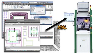
The Hesse Mechatronics Utility Module creates an XML data file that contains wire bond information of polylines in a DXF/DWG file. This XML data file can be used with Hesse Mechatronics wire bonding machines that accept XML data format. This can be done on the Wire Bonders BJ820, BJ935 and BJ939.
- Multiple bond wire groups can be set with unique references.
- Sequence numbers and direction arrows will be visible in the drawing.
- Create individual bond wire reference blocks.
- Update existing blocked entities such as the dies or chips with reference points that will be included in the XML output.
- Assign a name for the Bond Wire Reference (BDS) for selected wires.
- Assign the Reference a Sequence Number (BDR), which controls the order in which each will appear in the exported XML file.
- Assign a parent name (DEPENDON) to use as a reference system.
- Set a symbol text (REFP1, REFP2) to be used as a first and second reference point.
- Add direction arrows and sequence numbers to the drawing and set size of text and arrow size.
- An array of wirebond data can be exported when an array of identical parts is being wirebonded.
The following parameters are available:
- Set a Pitch of the array in the X (horizontal) dimension.
- Set a Pitch of the array in the Y (vertical) dimension.
- Set a Quantity of arrayed parts counted in the vertical dimension.
- Set a Quantity of arrayed parts counted in the horizontal dimension.
Share:


