Key Target for SMT Manufactures is to provide efficient manufacturing process with resulting High First Pass Yields. Lean manufacturing with good strategy for process improvement provides the greatest benefit for process stability and consistent high first pass yield. Identification of process errors requires high quality information from different stages of process combined with capable process tools to identify any process defect.
Kevin Youngs, Key Account Manager, Omron Europe B.V.
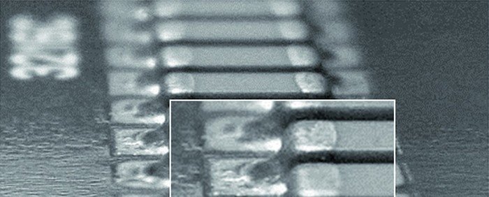
One area of process that yields potentially the highest rate of failure at the end customer is the solder joint. The number of solder joints is increasing due to the increasing high density designs of modern day products. CAD design of PCB’s tend to be focus on ‘Design for Manufacturing’ resulting in insufficient design of land geometry and positioning. As a consequence, inspection of the solder joint becomes a challenge for any Automatic Optical Inspection (AOI) System, but it is the AOI system that provides the essential information for process control.
Issue for PCB solder joint inspection
The most important issue in today’s production is to reduce false call. Reducing false call means to improve inspection accuracy, which is particularly apparent in the automotive sector. However, non-detection (escape) is the worst issue as the cost of product failure increases towards the back end of the process, after reflow inspection. In this case, if product failures would flow out to market, the cost of future would lead to addition failure repair cost including cost to change the manufacturing process and even loss of business. Therefore, the key objective of any AOI system is to capture all defects, but achieve low false calls.
Another area of false call is caused by an over load at the verification station. High false call rates from an AOI system will inevitably result in escapes from the verification, which leads to a critical situation concerning quality assurance of customer products. The root cause of false call can be attributed to the capability of the illumination and image capture system to measure solder fillet. In addition to accurate measurement of the fillet shape, are obstructions such as shadow, reflection and inspecting configuration, which requires an engineer to teach the difference between OK and NG sample. For this, a lot of failure sample are needed to complete programming, in turn influences the false call. To resolve the issues of programming, it is important to justify criteria by making SMT quality to be quantitative. To achieve SMT quality to be quantitative, 3D sensing technology for both solder shape and component is necessary.
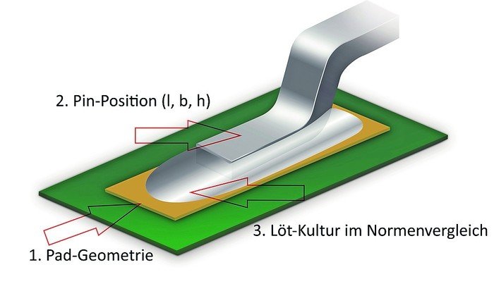
To inspect an SMT solder joint accurately, it is important to develop image processing technology that is defining SMT characteristic. To achieve this aim, an exact land position is very important, the reasons are due to PCB expansion after reflow process, which cause change land position, and X,Y position under the inspection camera may change due to variation in stop position. Software correction by measurement is the key technology as window shift cause false call directly
High quality fillet recognition
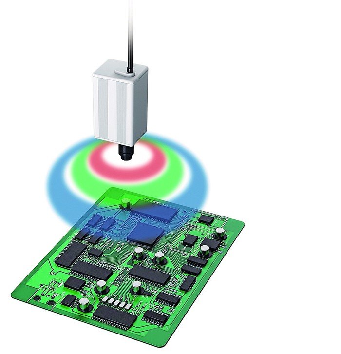
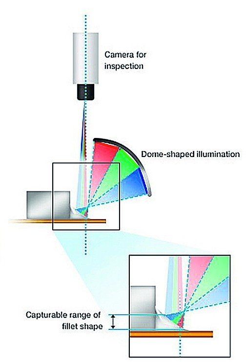
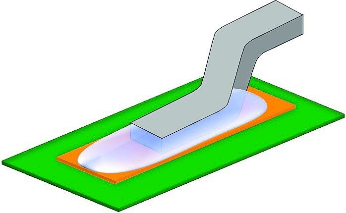
RGB color lighting reflects from surface of the solder joint, where the angular reflection precisely captures the shape of the fillet. The preciseness of the fillet shape is a result of the color highlight dome shaped illumination, which can irradiate in a broad angular range of 360degs. Omron understands the fact; this is the only method to provide accurate reflective information to the camera for image processing of fillet information.
Accurate fillet measurement
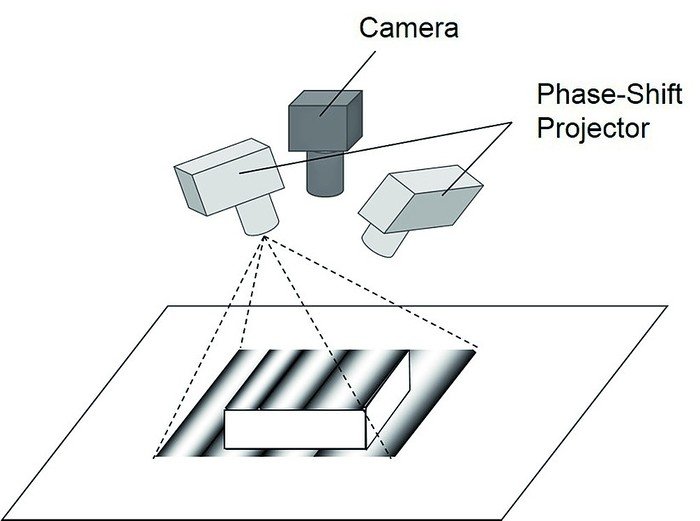
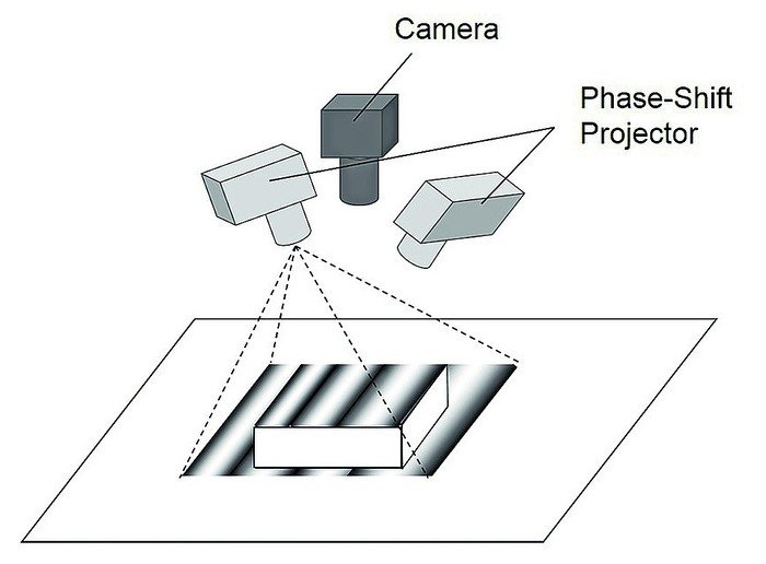
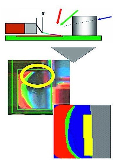
The company’s knowledge through vast experience proves that capturing electrode posture accurately is an essential. The electrode must be correctly positioned with respect to the land to enable high accuracy of fillet measurement. We often see a component color that is similar to PCB color, or often electrode color similar to solder color, in these cases it is difficult to capture the electrode precisely. Solving this issue requires an addition measurement method utilizing 3D Phase Shift technology, for half-mirror surface combining color highlight method for mirror surface.
On its own, Phase Shift lighting technique has a limiting effect to precisely capture the shape of the solder fillet. This is due to the limited spread angle of the irradiated light on the fillet mirror surface shape, which leads to distortion of the measured quantitative, thus concluding that a Phase Shift Lighting and calculation method is reflected in a narrow range, rendering Phase Shift method as not suitable for the measurement of the mirror and curved surfaces such as solder fillets. However, Omron unique knowhow proves that Phase Shift illumination can be utilized to measure points of the fillet shape and utilized in combination with color highlight system can provide high accuracy measurement of the fillet shape.
Electrode lead posture position
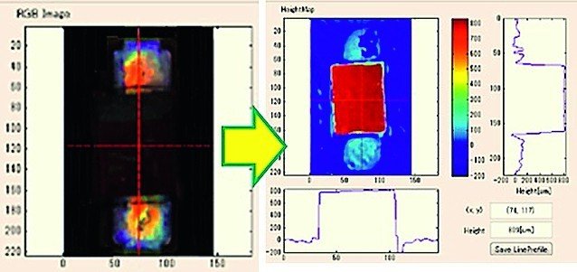
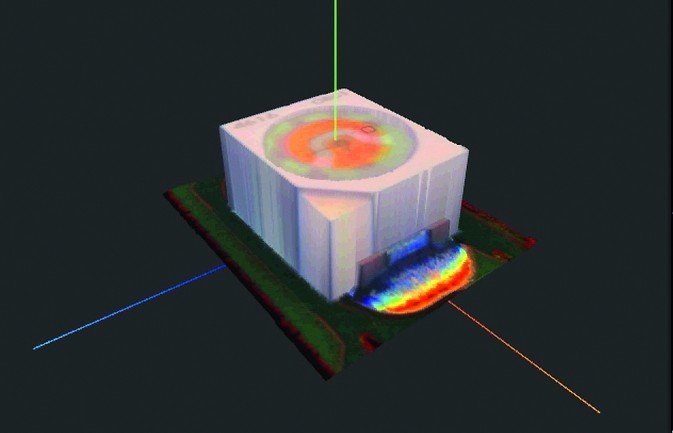
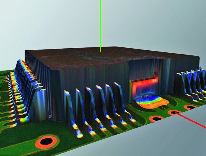
A method to detect land and electrode precisely, solder volume and wettability, must be checked to confirm electrical reliability. To check solder volume and wettability, 3D sensing technology is essential because the monochrome image processing technology is not enough, but still used in some AOI systems. The 3D color reconstruction technology, which can realize measured solder height and length is the proven method for high quality and reliable inspection.
Usability of the inspection program
Inspection capability is deeply relate to usability of the programming station, which is relating to programming, and especially fine-tune process, depend on inspection configuration. Programming using a form of CAD import data is the preferred method for initial program creation. In some cases, Gerber data is used to register the geometry of a land surface. However, if we define programming as making program to fine-tune, current methods are not enough as there is always a GAP between design and real PCB (component size, electrode length, land size etc.). Fine-tune which is to meet real PCB situation (reflect OK image characteristic etc.) is mandatory at the final stage of a highly reliable program. Problem is operators are required to input processing language although quality standard strictly define such as “height, length and width”.
In most cases, it is almost impossible to translate quality standard into image processing language, therefore, operator always have to set criteria according to OK sample and NG sample, with regardless quality standard.
To make fine-tune process simple providing a highly accurate program, it is necessary to put quality standard (solder height, length, width) instead of image processing language.
Again, 3D sensing method is essential for usability. With this process inspection criteria must be reasonable and never confuse by uncertain OK/NG sample. In addition, IPC-A-610 is asking for quality with definition quantitatively. For this, land position, electrode posture, solder shape 3D measurement is mandatory.
Effects of shadow
Shadow is a contributory factor for false calls relating to the fillet measurements. The direction of angular illumination can be interrupted by tall components casting shadow to the smaller component, such as Chip and IC. When the quantitative, measurement of fillet is obtained, the effect of shadow can be removed.
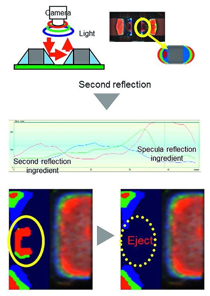
Effect of reflection
Reflection is another common contributory factor for false calls in high density PCBs. The direction of angular illumination is reflected from mirror components such as electrolytic capacitors and adjacent fillet from chip components. The result of accurate quantitative, measurement of solder fillet can result in the removal of shadow effect.
productronica, booth A1-538
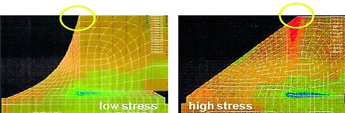
The importance to measure the shape of the fillet shape is to ensure good electrical connection and mechanical bonding.
Share:


