Stencil printing requires a higher degree of equipment accuracy than ever before, as precision becomes increasingly difficult to maintain when higher speeds and throughput test the limits of machine capabilities, particularly with tiny apertures and tight land patterns. Therefore, equipment design engineers are tasked with the requirements of tighter tolerances and accuracy. Have a look at defining and verifying the accuracy of printers, and how precision relates directly to your SMT process.
Michael L. Martel, Speedline Technologies, Inc., Franklin, Massachusetts, USA
Printer accuracy must first be defined in terms of real and measurable parameters and then verified. Different tools are used to confirm printer accuracy; these include MCA (Machine Capability Analysis) and PCA (Process Capability Analysis), both of which are typically administered by 3rd party companies. Printer manufacturers may also have in-house accuracy checking tools designed to verify the precision of their machines. And in production lines we may find systems that communicate with a solder paste inspection (SPI) machine, designed to automatically correct registration errors based on closed-loop feedback.
Greater printer accuracy has always been a key goal of the engineers. In the early days of SMT, when technology transitioned from hybrid circuits printed on small squares of ceramic substrate to FR-4 epoxy-glass, accuracy became a factor as board size increased. Those early SMT assemblies were single-sided, with the largest component typically a 20-pin QFP with J-leads on standard-pitch land patterns. The average size of these boards was perhaps 6 inch square, but this was still much larger than a hybrid circuit device. As the surface area of PCBs increased, so did print registration problems. Back then, wire mesh screens were used for printing solder paste, and they stretched during the print stroke due to squeegee pressure. This technique was followed by stainless foil stencils that were still mounted in a flexible border; a better solution, but not enough. Today, stencil foils are mounted now directly to the frame. The focus on accuracy has turned toward the stencil printing machine, as PCB-assemblies became more compact.
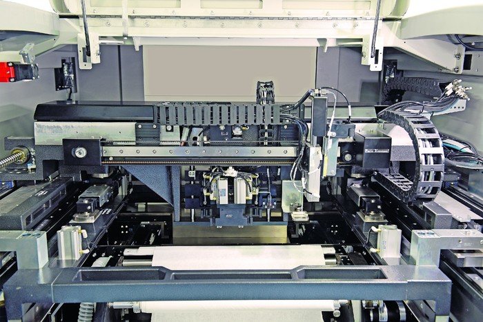
Unlike some other workstations in the SMT line, the stencil printer is probably the most complex and multi-featured next to the pick-and-place equipment. The printer features many moving parts, and many elements to each cycle that is part of the successful paste-printing. The PCB indexes into the machine, is positioned and/or clamped in place, often with the aid of programmable support tooling. Then vision alignment of stencil to board follows, the lowering of the squeegee blade to the stencil and finally the print stroke. This is of course an oversimplification, because within each cycle the following steps are all involved and exercised with high precision: including paste kneading, print-stroke speed and pressure adjustments, paste addition, and Z-axis motion of the stencil, frame and squeegee head. For a very high accuracy print that has to be utmost repeatable from board to board, all of the machine parts that are involved in motion must be manufactured and machined with absolutely tight tolerances. The effects of out-of-tolerance parts are cumulative, and are reflected in the accuracy and repeatability.
But do I need this much accuracy?
It may seem hyperbole, but there is no such thing as a printer being ‘too accurate.’ Even though common consensus in the industry is that one should never purchase excess capacity or capability that isn’t needed or may never be needed, ‘accuracy’ with a printer isn’t the same as board-size handling capacity. A new printer is introduced to the market with 8 micron alignment and 15 micron wet print repeatability ( 2 Cpk @ 6σ), significantly more accuracy than current available models. The engineer who is shopping for a new printer might say, “Our company standard specs only require 25 microns @ 6 sigma 2 CpK, so I don’t need such high precision.” But, in fact, he does, because higher machine accuracy means a greater ‘cushion’ of tolerance room to accommodate variations in other elements in the process. To the tolerances of a printer we must take into consideration variations in batches of boards/fiducials, variations in stencils and any variations introduced by other process elements, whose effects on the overall accuracy of the process are cumulative. Variations must be added together; the sum will be the true accuracy.
Accuracy factors
Printer accuracy begins with machine design. A structurally stable printer is key to maintaining repeatable accuracy at high speeds when the acceleration/deceleration forces of mechanical parts within the machine are greatest. Stability dampens vibration, which itself can negatively affect accuracy when such tight tolerances are being maintained. Rigid positioning of the PCB is also critical; one does not want it moving at all once it has been aligned with the stencil. For this reason, PCB clamping systems have been developed that keep the board tightly secured during print processing. One such system uses a side snugging technique. Flippers engage to secure the board across the top edge, which ensures board flatness, and removes any warpage from the board. The Z-tower raises the board to the programmed height based on board thickness, software-controlled snuggers clamp the board edge across entire length of the PCB, and then the flippers retract so that there is no interference with full board-to-stencil contact. This technique addresses two issues: the first being rigid positioning of the board for optimum accuracy, and the second is achieving optimal stencil-to-board gasketing for a good print. This approach is especially well suited to thin PCB printing. Another design-related contributor to printer accuracy is reduction of unnecessary motion of parts and units in the machine. For example, reducing the Z-axis height travel for the print head, if that amount of travel isn’t needed, can enhance stability and, again, reduce vibration for improved accuracy particularly at high speed, high throughput printing. To be sure, the accuracy of a stencil printer is not solely decided by the precision employed in machining its various moving parts. The value of a production printer is in perfectly processing hundreds and thousands of boards that follow with the same quality outcome as the first. Thus, different factors affect long term and continued accuracy. One of these is the control software which directs the machine as well as assist in keeping it operating optimally. Many different factors can contribute to a printer ‘drifting’ out of registration over time; these range from the aforementioned machine tolerances to temperature changes in the manufacturing area, stencil stretch and deformation and more. Most can be addressed to some degree but not eliminated. Thus, keeping the printer ‘on course’ can be achieved by occasional printing process checkups using automated inspection technologies such as solder paste inspection (SPI).
SPI and closed-loop feedback
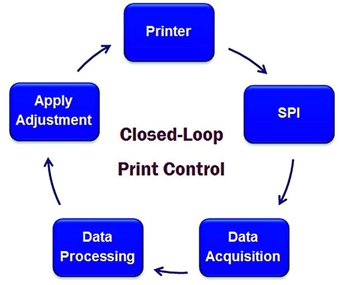
SPI directly downstream of the printer automatically checks the printed board for paste height on pads, paste insufficiencies, bridging and other defects that are a result of problems in the process that don’t all have to do with print registration, but misregistration is one of them. Software and advanced communications allow the SPI machine to interact directly with the printer through a specially-developed common interface. Simply put, when the SPI machine ‘sees’ X, Y and Theta offset problems on PCBs, it analyzes the data almost instantly and instruct the printer to correct those offsets, automatically and ‘on the fly’ without requiring operator intervention. Big changes aren’t made all at once; each time a PCB is printed, the offsets are incrementally corrected until, after a few boards, print deposition is ‘zeroed in’ precisely where it’s supposed to be on the pads. This is especially useful for fine pitch/fine feature print process optimization. However, if a printer is not working to factory specifications or is out of adjustment, inspection and closed-loop feedback will be working overtime and never get the printer operating consistently well or repeatably, at least not as much as it should. The printer quite literally doesn’t ‘know’ that it is out of adjustment. This is where MCA comes in.
Machine Capability Analysis (MCA)
A machine process capability analysis confirms printer performance in term of mechanical accuracy and stability. This test proves the stability (repeatability) of the printing process using specific tools. Manufacturer specifications are used to qualify the equipment. This is important because a printer manufacturer can ‘claim’ any machine accuracy they want, but MCA testing, especially independent 3rd party testing by a reliable and professional company proves and verifies a printer’s accuracy without any ambiguity. There are two types of MCA testing employed to learn whether or not a printer is ‘mechanically’ accurate when printing. One method is home-grown; the other involves testing by a 3rd party. And, while an advantage to using 3rd party testing is that it is an unbiased, dedicated and independent method, it is expensive to use frequently. In many cases, printer OEMs will purchase the testing machine and its dedicated glass plate fixtures to perform tests within their own facility on new machines or ones that are being refurbished or rebuilt. But this doesn’t solve the customer’s need for frequent, affordable testing for print process optimization. There are tools such as one printer manufacturer’s accuracy checking system.
Printer accuracy check
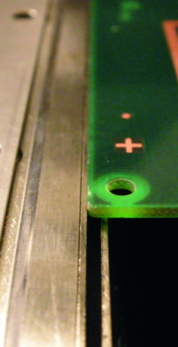
The ‘homegrown’ printer accuracy testing method developed by one printer manufacturer enables the user to quickly and inexpensively verify the precision and repeatability of the machine. Since it is an option built into the printer, it’s available any time and is far less expensive than 3rd-party testing, but is not as precise a verification. Eventually, one may have to bring in 3rd party testing (audits) but using it reduces that frequency significantly. This ‘homegrown’ method uses the alignment fiducials and print verification pads on the user’s PCB to verify alignment accuracy. These verification ‘locations’ are user-definable, as are the users’ upper and lower process limits. A customer inputs these locations and limits when launching the program. It measures targeted paste deposits and compares them to the verification locations using the printer software and machine vision. It will automatically locate both the pad and the paste model simultaneously resulting in a measured print offset. How accurate is it? The method was proven accurate by the OEM by comparing the print verification data generated by the test to years of 3rd party (CeTaq) data before the option was released for customer use. While not a replacement for independent testing, it does give the users the ability to know that their printer is performing accurately and reliably on a daily basis, to user-set tolerances based on test PCB or actual production. This testing measures performance. Should results begin to vary or accuracy to wander outside of acceptable tolerances, it may be considered an ‘early warning sign’ that the printer needs examination by the factory or authorized distributor professionals. The testing provides the user with the data of machine performance repeatability. Total machine accuracy can and is influenced and adjusted by software. Accuracy is important for precise offset-free printing but is not built into the machine, as is repeatability. Thus, this test is essentially PCA where as MCA measures the innate accuracy that is built into the machine. Evaluation of a printer’s accuracy and process potential must include both, ongoing.
Integrity of the MCA system
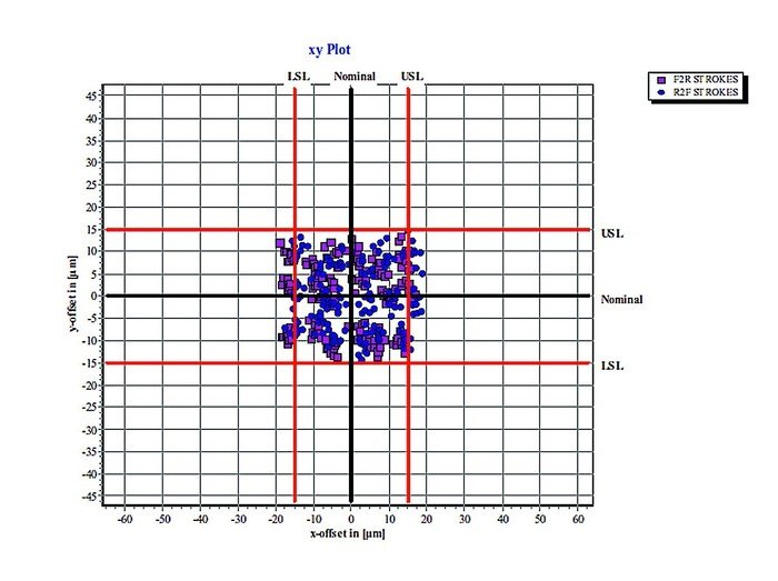
With the CeTaQ test procedure, the stencil and squeegees are installed and configured in the machine. The board is loaded and clamped, fiducials marks are identified by the camera. Once the board is printed, the glass board is inserted into the testing machine which measures the positioning accuracy (XY) and evaluates the results. A minimum of 6 boards are printed and measured. Results are then pooled together and analyzed depending on printing direction. Printing offsets of angle between board and stencil can be determined at this state. Some corrections are applied into the machine software (XY, Theta) and a batch of boards are printed again. Once the corrections are done and the process became stable, a minimum of 20 printed boards without any process/machine modifications is necessary to evaluate the stability of the process. When the measurement is completed, statistical results and graphical analysis are exploited to evaluate the machine performance. The stability of the process is proven. The machine is able to print product within the original specifications set forward by the manufacturer. The measurement system and glass boards are calibrated using international metrology standards. Most importantly, the testing ensures that the printer is performing within the specifications.
The 3rd party-administered MCA testing for unassailable verification of performance claims is necessary simply because when selling machines in a competitive market, one must back up claims that, at first glance, might give one pause, particularly in a market where printer manufacturers (and others) can claim any level of ‘process accuracy’, but this term is essentially meaningless. The new printer features capability and performance specifications that, when compared to current top-of-the-range SMT printers, are literally ‘off the charts’. This printer has proven, through independent 3rd party MCA testing and verification, 8 micron alignment, with 15 micron wet print repeatability ( 2 Cpk @ 6σ). This represents a 25 % improvement in wet print accuracy over current best-in-class machines.
SMT printer accuracy has become a more important issue than ever before as components and land patterns shrink and PCB topographies become denser. Accuracy is a function of design and engineering, and can be measured and verified using MCA tools and testing. Process capability is also measurable and can be enhanced by software and the aid of external systems such as closed-loop communication with an SPI system and mechanical performance validation, on occasion, through accuracy check tools. Variations in different elements in the printing process, e.g., PCB fiducials, stencils and others ensure that there is no such thing as a printer that is ‘too accurate’ for any SMT assembly application; rather, a high degree of accuracy combined with tight control and optimization will ensure a robust and repeatable process so that the user will obtain the full value of their production stencil printer.
productronica, booth A4-554
Share:


