If a test manager, after years of experience in a production environment, moves to operate in a depot repair site, he will have to review almost all of his practices for board testing. In fact, test requirements in a depot environment fully mirror those of a manufacturing facility.
Luca Corli, Director of Sales, Seica
In production most of the boards pass; if not, the test manager might have to investigate on the stability of the test program that can be cause of excessive FF (False Failures). In a depot the opposite is true, most, if not all the boards fail, so if too many NFF s(No Fault Found) occur, the coverage of the test program has to be questioned. In production little time is available for test program development and test time is critical. Not so in a depot, where the pressure to ship is not so high and volumes are low. Luckily the production test manager can quickly develop his test program starting from CAD data. CAD data are rarely available in a depot, and the test manager would be happy if he has at least a paper schematic s or a block diagram of the board to test. When we finally consider fault coverage, the two environments again mirror themselves. Production faults will mostly include shorts, lifted leads, missing components; inversely,, depot repair faults will tend to be defective components and PCB functional faults.
Rebuilding the CAD data
The first issue that a manager has to address to organize test in a depot environment, no matter what kind of test strategy he has in mind, is how to build up board information in the absence of CAD data. The solution calls for a process of Reverse Engineering that will enable him to extract, starting with a reference board, the layout, netlist and parts list information and rebuild the CAD data. Unless our test manager wants to spend endless amounts of time and energy with a voltmeter, pencil and paper and a lot of faith, he will have to look for the availability of automated solutions. Different proposals are available associated with board testers, with different levels of accuracy and completeness.
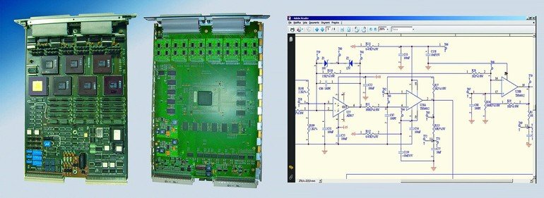
A 100 % complete and accurate Reverse Engineering process can be implemented using a Flying Probe (FP) as an automatic tool to collect and elaborate the required information. Note however that, in order to achieve an accurate reconstruction, the FP would need to electrically access the board on BOTH sides simultaneously, otherwise some net connections would be missed. Here is a real example of how to proceed, step by step, using a dual-sided FP to complete Reverse Engineering of a PCB. The process will start by putting the reference board onto the FP, and taking pictures of both sides of using the FP cameras, to be able to assign XY coordinates to each component lead, test points, etc.
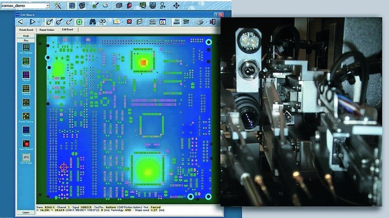
Now the FP, knowing the position of all the PCB points to access, will automatically execute a series of tests and measurements to identify all of the NET interconnections on the board. The reconstruction of the complete net list of the board is the first, fundamental step of the process. At that point, an interactive graphic environment will allow the test engineer to place component types and values on the layout and to complete the parts list. A complete test program can now be developed on the Flying Probe, including both power-off and power-on structural, in-circuit and functional tests with precise diagnostics.
Of course, with appropriate tools, more can be obtained as a result of this effort. The reconstructed CAD data can be exported via EDIF 2.0 to a workstation thus allowing preparation of complete electrical schematics for documentation or as a support for other stages of functional test. The process can even go further: routing and placement of the components can now take place on the workstation and ‚clones‘ of the original PCB can be manufactured.
Flying Probe with high coverage
Use of a FP in a depot environment is a growing trend. Unlike the FPs of the past, mainly limited to performing quick prototype test or to act as manufacturing defect analyzers (MDA) before in-circuit or functional test, the capabilities of the FP have now substantially increased. The addition of power-on test tools, the extensions to embrace JTAG or on-board-programming (OBP) make the FP a serious contender, on low/medium production volumes to replace bed-of-nails in-circuit testers. Furthermore, new tools specifically targeting depot test problems have been designed to be used with the FP. Test and diagnostic techniques to push-pull current on a net to detect stuck-at faults, thermal analysis to detect too-cold or too-hot faulty components, functional quad-pole verification using DSP instrumentation, and ,when needed, the addition of fixed I/O analog or digital channels make the FP a powerful depot test ATE.
Given that a modern FP would be invaluable for the Reverse Engineering task and to improve PCB repair cost and effectiveness, with no fixture, fast test generation and high coverage, in a military depot this level of test could be acceptable only if the depot has the ability to follow the board test with validation on the target equipment (second level test). Second level test will certify the board as ‚ready-to-fly‘ after the repair operation. Availability of the final equipment in a depot is rarely the case, and comprehensive functional test of the PCB on a high performance ATE is therefore necessary. Again, our test manager will be challenged by new problems with respect to his manufacturing experience. Simply stated, the life of the weapon hosting the electronic cards to be maintained is by far longer than the life of the usually Commercial-Of-The-Shelf (COTS) test equipment dedicated to the task. Take the General Dynamics F-16 as an example: the first flight was in 1974, first deliveries in 1978, and today it’s still flying and in production. At least three generations of board testers have lived and died across this life span, thus forcing expensive ATE and TPS migration processes to assure test Legacy Replacement.
Legacy Replacement of obsolete ATE is the major cost in a depot, not so much for the investment on the new ATE, but for the associated costs of migrating hundreds of test programs and test fixtures. Here are some guidelines to help planning for such operations:
New ATE performances
- The choice should assure that the architecture of analog routing, digital level selection, timing flexibility and overall capacity matches at best the ATE to be replaced
- The choice should assure that, together with performances for new technologies, the old requirements are covered: wide range of digital levels, analog and digital guided probe diagnostics, fault dictionary, links to test simulators, etc.
- Robust hardware and software environment, but open to other repair solutions
- Vendor support and long-term commitment to military and avionics business.
- Availability of a robust conversion environment to assure flawless TPS translation and minimal debug
- Facilities to migrate or replace GPIB or VXI instrumentation and associated drivers
- Turn-key migration services and experience
- Rebuild fixtures if economically convenient
- If old fixtures have to be maintained, strongly avoid superposition of fixture adaptors; better to look for solutions that engineer direct test access with the original receiver.
Test programs migrations
Fixture migrations
In summary, depot board test requirements are new and different from a manufacturing environment and represent a serious challenge for the test manager. The solution to look for should provide the best bridge between the heritage of the past and the needs of the future, careful planning and partnership with an experienced, long term committed supplier.
Share:


