
Standard fluid dispensing systems involve a dispenser valve mounted to the XY gantry, which is movable to dispense patterns at desired locations onto the substrate, and is positioned in horizontal XY plane, through the conveyor system. Dispenser valve can be positioned in the three-dimensional space, dependent upon the component’s orientation on the substrate. The gantry system is driven through a drive mechanism and controlled through a motion control system. To dispense a pattern, the controller determines the location and orientation of each substrate through a camera system mounted on the gantry system itself.
The camera system does the vision capture of reference points or fiducials located on top of the substrate, through a pre-programmed path set in the dispense process program. Captured vision images of the reference points determine the location of the substrate, in the XY coordinate plane. Height sensing is performed through a height sensing laser, mounted on the gantry, to determine the dispenser valve needle tip position from the substrate. The motion controller then positions the dispenser valve at the XY programmed location, followed with the dispenser valve needle tip coming down to the programmed dispense gap from the substrate. At this point, the dispenser valve starts dispensing a pre-programmed fluid pattern onto the substrate.
Advances in dual head dispensing
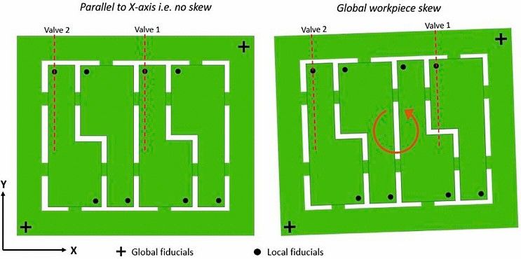
To optimize the line throughput, dual dispenser valves pitched at a desired distance are used to dispense identical substrates synchronously. If PCBs are panelized in a single processing panel then all the PCBs must be rotated in the horizontal XY plane. First and second substrate alignment can be found through global reference points or fiducials located on the body of the panel. Existing dual dispensing methods automatically realigns patterns to make a one-time automated adjustment of valve 2 relative to valve 1 prior to dispensing, and only considers the global skew. Therefore, both identical PCBs get dispensed synchronously, based on global skewness.
Dual head dispensing has been driving on a single Z-axis to dispense identical patterns with each dispenser valve synchronously. Most of the existing techniques only considers the lateral shift of the second identical pattern in either X or Y direction but not the part-to-part rotation. Lateral shift is generally considered with the fixed micrometer adjustment on either X/Y or both directions on the mounted dispenser valves, prior to dispensing operation.
Conventional dual dispensing methods do not incorporate the dynamic real time adjustment of both heads during active dispensing onto the identical substrates. If parts are skewed to each other in a tray and only global skewness is considered, then the dispense pattern gets misaligned. Only global fiducials are captured which defines the global alignment of the tray/board leaving behind the part to part rotation of individual parts in the tray. For part to part rotation, movable gantry system is required to capture the local fiducials or reference points through the camera vision system for each individual PCB. Parts can be locally skewed due to improper tooling or substrate sized smaller than the carrier pocket tray where the part is seated. Therefore, conventional dispensing methods are uncapable of active correction, to consider the skew angle and scale factor locally. Scale factor is based on where the gantry vision system finds the fiducials or reference points in comparison to the programmed locations in the process program. Mounting each dispenser valve on an individual Z-axis drive system provides the capability to compensate for part-to-part rotation through the local reference points or fiducials. Part to part rotation considers the skew factor and scale factor for each individual PCB.
The machine gantry system is configured to provide movement in XY direction with the first dispenser valve coupled to the gantry for dispensing. A second dispenser valve is coupled to the gantry through the automatic adjustment mini drive system to drive the second dispenser valve for dispensing. A mini XY drive system is mounted and configured onto the second Z-axis to move the second dispenser valve in XY direction, to manipulate spacing between the first and second dispenser valves. A controller controls a dispense operation of the first dispensing valve on the first electronic substrate pattern and a dispense operation of the second dispensing valve on the second electronic substrate pattern.
The mini drive system includes a linear bearing secured to the gantry and mounting block, configured to ride along the linear bearing, and coupled to the second dispensing valve. The automatic adjustment mechanism includes a first linear drive motor assembly configured to move the mounting block along the linear bearing. The first linear drive motor assembly includes a ball screw driven linear actuator, which is driven by a mechanically coupled motor. The automatic adjustment mechanism further includes a first bracket secured to the mounting block, the first bracket extending in a direction perpendicular to a direction of the linear bearing, and a second bracket secured to the second dispenser valve and configured to ride along the first bracket. The automatic adjustment mechanism also includes a second linear drive motor assembly configured to move the second bracket along the first bracket. The second linear drive motor assembly includes a ball screw driven linear actuator, which is driven by a mechanically coupled motor. For each of the first dispensing unit and the second dispensing unit, the automatic adjustment assembly also include a Z drive mechanism configured to support and lower the dispensing unit when performing a dispense operation with the first dispensing unit.
Technological advantages
Multiple independent dispensing systems are sometimes used to increase the production of dispense operations. This solution is often expensive, requiring multiple machines, additional manufacturing space and in some cases multiple machine operators. In typical operations, manufacturing floor space is both limited and expensive. It is therefore desirable to reduce the „footprint“ of each manufacturing system on the manufacturing floor and to reduce the number of separate machines that need to be operated and maintained.
For some applications, multiple instances of the same circuit pattern are fabricated on a common substrate. A common example is a circuit pattern for a cell phone, wherein four or more patterns may be disposed on a single substrate. In such cases, there is often a fixed and uniform offset between the multiple instances of the circuit patterns, which may be disposed on a common substrate and separated from one another after completion, along the perforations. Furthermore, it is known in the industry that a dispensing system with multiple dispensing units or pumps may be utilized to increase throughput. In such systems, the offset distance between the multiple dispensing pumps may be adjusted to be substantially the same as the offset distance between the multiple circuit distances. If the accuracy of this offset adjustment is within the accuracy requirements of the resultant dispense pattern, then the multiple dispensing pumps can be positioned simultaneously by a single X, Y, Z gantry and operated simultaneously.
Experimental set-up and analysis
The main objective of this research is to conduct a detailed study to match the positional accuracy of the fixed right dispenser valve to the left dispenser valve mounted on the mini XY drive system, along with good dot and line dispense quality. The study involves the use of a high-speed dispensing system with a pneumatic jet pump installed, which can currently dispense material in a repeatable manner without affecting the dispense quality.
It begins at a point of performing the experiment on a pneumatic jet pump. A nozzle heater was used to maintain the fluid temperature equivalent to ambient temperature conditions. It concludes by running the experimental run to determine the dot and line positional accuracy to confirm the robustness of the mini XY drive system with minimal effect on dispense quality. This involves the use of glass jig plates to perform the dot and line positional accuracy tests.
Dot positional accuracy
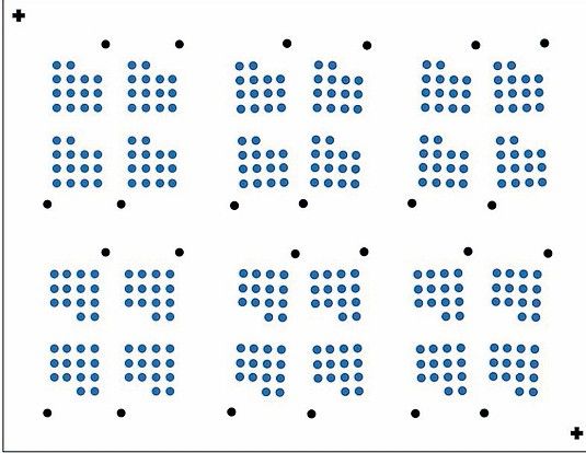
Dot positional accuracy is measured as the difference between the commanded position and the actual dispensed position for each individual dot, through dispensing an array of dots. Positional accuracy also defines whether the dot can shoot vertically or not (i.e., downwards) from the needle tip onto the substrate. From the customer’s point of view for field engineering applications, the dispensing should allow for certain dot characteristics, such as good shaped circular dots with good positional accuracy. Measurement of dispensed dots on the glass jig are performed with the optical measuring machine, through back lighting to measure the shift in XY direction. Each head needs to dispense 84 dots for each orientation type. The orientation type displayed, resembles the smartphone manufacturing board, which generally has patterns oriented either at 0 degree or 180 degrees. Height sensing is performed on the glass to ensure correct dispense height from the glass jig top surface. Each pattern is rotated either clockwise or counterclockwise by 2 degrees to prove the left head dispense accuracy is equivalent to the right head in real synchronous mode dispensing.
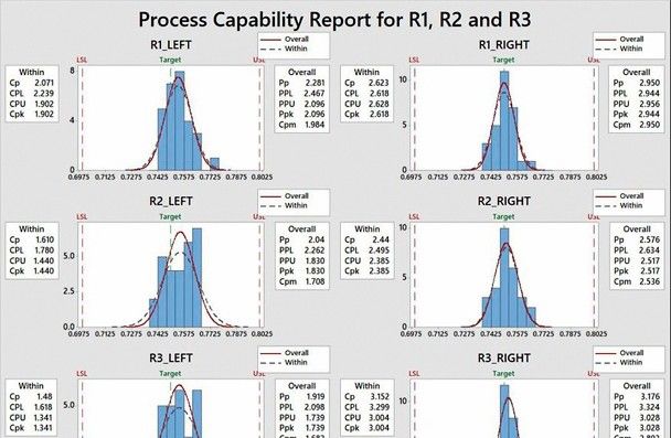
Process capability index, Cpk measures how close the process is to the target and how consistent the process is around its average performance. An operator may be performing with minimum variation, but he/she can be away from his/her target towards one of the specification limits, which indicates lower Cpk, whereas Cp will be high. For both the shifts, high value of Cp and low value of Cpk indicate that the process has a centering problem. A generally accepted minimum value for the indices is 1.33 according to industry guidelines to determine whether the process is capable or not. Process capability is determined for ± 50 microns specification limits at ± 3 sigma capability. Cpk values are also much higher than the industry acceptable standard for both heads in real time dynamic dispensing in synchronous mode.
Line positional accuracy
Line positional accuracy is measured as the shift between the commanded location of the programmed line to the actual dispensed line. Line comprises of series of dots stacked together at a correct spacing and align properly to form a straight and non-scalloped line. Once the dots touch each other, the boundary is scalloped but the dots are compressed further, and fluid takes the shortest path to the deepest scallop, to form a perfectly straight line. The closer the dispense valve is to the substrate, the better the line quality.
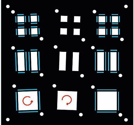
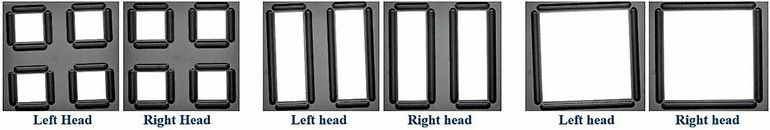
Experimental test was performed on the glass accuracy plate. Patterns on the left side are skewed at an angle of 1.5 degrees in counterclockwise direction, while in the middle patterns are skewed at an angle of 1.5 degrees in the clockwise direction. Patterns on the extreme right side are not skewed at all. Pattern on both extreme sides are pitched at 44 millimeters. Fiducial alignment is performed before dispensing the lines around the edges on the chip. The machine vision system locates the chip edges through a vision algorithm and dispenses line patterns along the chip edges at the programmed position offset. Position offset is defined as the offset distance away from the center of the chosen chip edge, in the direction perpendicular to the chip edge. Lines highlighted in blue color are dispensed at a position offset of 0.75 millimeters from dispense height of 2 millimeters. Patterns are dispensed with both heads in synchronous mode with the mini XY drive system set-up.
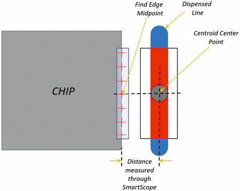
A metrology tool named SmartScope has been programmed to measure the distance between the center point of the programmed centroid on the dispensed line and the midpoint of the programmed chip edge. Specification limits are based on tolerances of ± 50 microns around the 0.75 millimeters position offset.
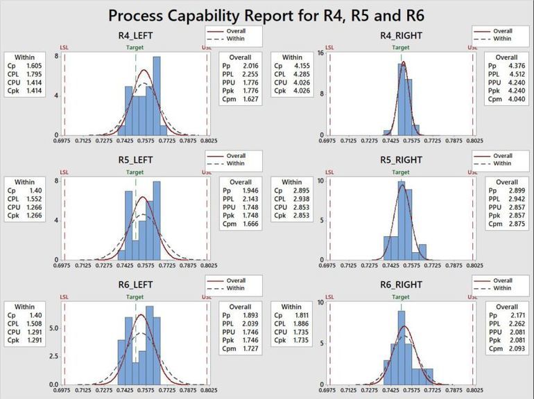
Results showed that the standard deviation of the left head to be quite close to the standard deviation of the right head on most of the runs. Process capability is higher than the 1.33 value which is the industry acceptable standard for both heads in real time dynamic dispensing in synchronous mode. The right head has a little bit higher process capability than the left head due to its fixed mechanism onto the right Z-axis, while the left head is mounted on a movable mini XY drive system on left Z-axis.
Dispense quality
Line quality depends on the dot characteristics in terms of dot positional accuracy and circularity. Line width is defined by the series of dots dispensed at a correct spacing to align properly to form a straight and non-scalloped line. Visual inspection relates to human-based optical inspection of line quality under the microscope to capture any satellite formation during the dispense cycle. Visual inspection also helps to determine whether the lines are misaligned or not and the lines are fine across the edges. Line quality shows both heads have good dispense quality in dual head synchronous mode.
Increased throughput
Increased throughput in the production environment has been a significant factor to meet the required units per hour (UPH) set mostly by the electronic device manufacturers to satisfy the customer’s demand. UPH is used to measure an industrial production process in terms of how many units produced per hour of the final product. Some of the major factors contributing to throughput are better vision capture and imaging system, conveyor mechanism, powerful software-controlled architecture and laser height sensing which is mounted on a more precise and faster platform to deliver consistent dispensing results.
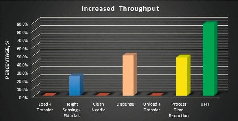
The cycle time calculation does include the time interval for the board transfer, board clamp, capture board fiducials, height sensing, clean needle, dispense, board unclamp and transfer downstream. Total process time went down by 46.75 percent which is quite close to cutting the process time to half, from switching single head to dual head with mini XY drive system. The cycle time and UPH calculation involves dispensing operation of one carrier containing 16 pieces of the product. Indicated UPH and cycle time percentages have been calculated through running a programmed test which includes lines and dot commands in the process program, to simulate the production environment at most of the manufacturer’s facility.
There was a 24.00 percent reduction in height sensing and fiducials feature scan while switching from single head to dual head with mini XY drive system. Dispense time went down by 49.18 percent, which is a significant saving, almost cutting down the dispense time to half with a switch to dual head dynamic dispensing. There is no savings with board load, clean needle, board unload and board transfer time as they have no effect on the process. The desired high actuation speed can only be achieved for a small interval of time, limited by gantry motion along the three axes and mechanical friction between the parts. UPH went up by 87.79 percent while switching from single head to dynamic “real time” dual head dispensing.
Summary
Dual dynamic dispensing with the mini XY drive system has brought a new level of robustness to the high-volume manufacturing. The offset distance between the dispensing pumps is adjusted dynamically in XY direction to be the same as the offset distance between the multiple circuit distances to attain the same level of accuracy as the dispensing system. This way the multiple dispensing pumps can be utilized to increase throughput without any defect count coming from the left head mounted on the mini XY drive system.
With Cpk numbers greater than 1.33 for both dot and line positional accuracy at ± 3 sigma capability indicates that mini XY drive mechanism does not have any adverse effect on the accuracy of the left head which in turn is close to the right head. Dual head “real time dispensing” with mini XY drive system has arrived, offering greater degree of process control with skewed identical substrates adjacent to each other thus providing good product reliability during the production run. Also, less manufacturing floor space required with almost dual increase in productivity.
ITW EAE
8860 207th Street West
Lakeville, MN 55044
Tel.: +1 (508) 520–0083
E-Mail: mtsc@itweae.com
Website: www.itweae.com
Mittels eines Mini-XY-Antriebssystem wird eine doppelte dynamische Dosierung für ein höheres Maß an Prozesssteuerung sowie Produktzuverlässigkeit während des Herstellungsverlaufs und bei weniger Produktionsfläche realisiert.
Un système d’entraînement Mini-XY permet de réaliser un double dosage dynamique pour un plus haut degré de contrôle du processus et de fiabilité du produit pendant le déroulement de la fabrication avec une surface de production réduite.
Система привода Mini -XY обеспечивает двойное динамическое дозирование для более высокого уровня контроля процесса, а также обеспечивает надежную работу продукта в процессе производства при меньшей производственной площади.


