Mature and readily-available technology exists to test electronics cables and wire harness of less than 10 ft (3 m). Testing cables of tens, hundreds, or thousands of feet makes new demands on the test equipment, test procedures, and for the operator to obtain accurate test data without damaging the equipment or endangering the safety of the operator. This article focuses on these issues.
Electrical difference between long and short cables
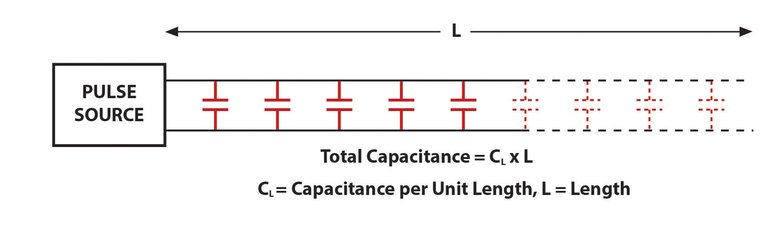
Capacitance makes a difference. Two or more insulated conductors that are bound into a cable develop capacitance between the conductors. This natural, unavoidable effect results from the proximity of conductors separated only by a thin layer of insulation. An electric field develops between parallel conductors, just as it would between plates of a capacitor. In this case, these plates are long, narrow filaments of copper. Capacitance will increase depending on the cable length, wire twisting, and presence of a shield around the conductors.
Good-quality twisted pair Ethernet cable has a capacitance of about 17 pF per ft. In the absence of an iron core or other material that concentrates the magnetic flux, which is located in close proximity to the cable, inductance only plays a small role compared to capacitance in affecting signal transmission through a long cable.
Increase of capacitance affecting wire resistance measurement
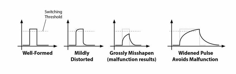
Acquiring data about wire resistance typically occurs by the application of short, DC pulses. The output impedance of the driver in combination with natural cable capacitance will create a parasitic low-pass filter. With high enough cable capacitance, it will drastically distort the measurement pulse and introduce error.
Wire resistance measurements occur at a low, fixed voltage, typically +10 V, and little opportunity exists to raise the voltage or lower the output impedance, in order to charge the cable capacitance faster. The pulse, however, can easily be lengthened to allow sufficient time for the pulse‘s test voltage to be reached before capturing the measurement on its falling edge.
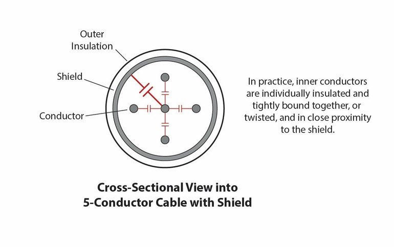
The capacitance picture becomes more complex when three or more conductors run in parallel through a cable, and especially if a surrounding metal shield exists. In this case, the capacitance between a wire being measured and its surrounding forest of copper can be much greater, accentuating the effect described above.
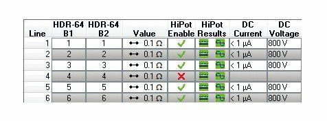
The impediments to a good measurement of wire resistance in the presence of high capacitance is overcome by simply waiting longer for the result. For cables longer than 10 ft. (3 m), the pulse width (dwell time) is increased as much as necessary to achieve reasonable data. Typically, resistance measurement of 64 individual conductors in a 2-ft-long multi-conductor cable will be complete in about 2 seconds on a CableEye test system, manufactured by CAMI Research. Lengthening the cable to 20 ‘ may require about 3 seconds, and lengthening it to 200 ‘ could take about 11 seconds for the result.
Increasing capacitance affecting insulation measurement
Ten feet of 22-gauge stranded copper wire has an ideal resistance of about 0.16 Ω. For good signal transmission, the lower the resistance the better. Wire insulation, however, has the opposite requirement – the higher the resistance, the better.
Making measurements on modern insulation, whose values are typically 100 MΩ or more at a thickness of only 25 mils (0.64 mm), imposes very different requirements on test equipment compared to measuring copper. While a low voltage of +10 V or less will push enough current through a copper wire to make highly accurate resistance measurements, hundreds or thousands of volts may be necessary to push enough electrons through good insulation to obtain a measurable current. Test equipment designed to do this is typically referred to as a hipot (high potential) tester.
When insulation resistance in Megohms (106 Ω) or Gigohms (109 Ω) is measured, the leakage current through the insulation can be found in microamps, at a specified voltage to compute this number. An additional test is aimed to certify that the insulation does not suffer dielectric breakdown at a specified voltage, which is typically a voltage higher than the one used to measure leakage current. Dielectric breakdown occurs when the insulation (the “dielectric“) ionizes (typically at a pinhole point in the insulation) to form low resistance conductive path through the insulator. Insulation which experiences dielectric breakdown will not only fail the test, but will render the cable damaged and unusable as the result of a small, open tunnel where insulation had once isolated the environment from the copper conductor.
As with copper wire measurement, a high voltage pulse was first used, but only the leakage current at this voltage was measured, which quickly created problems.
First, for the safety of the operator when high voltage test equipment is used, the maximum permissible output current is limited to 1.5 mA. In fact, in practice, the maximum limit, also called “trip current“, is preferred to be even less. Why? Should a pinhole opening in the insulation develop at a typical test voltage of 1,000 Vdc, the current will rapidly rise to the trip limit. Which means that at 1.5 mA, 1.5 W of power (1,000 V x 0.0015 A) would focus on an extremely narrow pinhole channel, with timing as fast as a lightning strike. The heat that is developed during the microseconds of a discharge could burn a hole in the insulation or vaporize copper on the wires‘ surfaces, permanently damaging the cable.
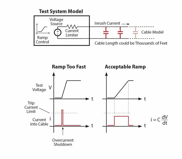
It is desirable to keep the trip current low. However, this may impose a cable capacitance restriction. The current that must flow into the cable, “i“, as the test voltage “V“ is applied, is a function of the cable‘s parasitic capacitance and the rate of change of the rising voltage, “dV/dt“: i = C dV/dt.
The shorter the rise time of the voltage (large dV/dt), the greater the inrush current needed to charge the cable‘s parasitic capacitance. If the ramp-up is too fast, the trip current is exceeded before the test voltage is reached, which results in the test system shutting the voltage down before a leakage measurement can be taken. This situation is indistinguishable from a true insulation breakdown where the trip current is also exceeded.
As a cable increases in length, so does its capacitance, which further limits the rise time. Thus, to reach the test voltage without first hitting the trip current, care must be taken to adjust the voltage ramp in accordance with the length of the cable – the longer the cable, the slower the ramp up.
The CableEye HVX Tester has a ramp that can be adjusted from 150 to 5,000 V/s. For cables not exceeding 10 ft. (3 m) and voltages not exceeding 1,000 Vdc, the maximum ramp rate will work well. The system has been tested on a cable exceeding 6,000 ft. (2,000 m) at a ramp rate of 150 V/s. Interestingly, the increasing wire resistance of such a long cable helped to slow the charging current, but also required a 10 second minimum dwell time. This ensured that the full cable length reached the test voltage prior to making a leakage measurement.
Insulation resistance testing in the presence of a shield
In a multi-conductor cable in a linear hipot test, high voltage is applied to one wire at a time with all other conductors at ground potential. The test advanced by incrementally stepping through each conductor, applying voltage, and making a leakage measurement. This maximized the likelihood of detecting an insulation flaw in the cable. The required total test time increases directly with the number of conductors (hence the word “linear“). In most cables, the capacitance is about the same between a conductor at voltage and all of the other conductors at ground, and in the absence of insulation flaws, the insulation resistance for each should also be about the same.
If a shield surrounds the conductors and must also be tested, the shield capacitance can be an order of magnitude higher than that of any other conductor, and current flow during ramp-up typically hits the trip current before the test voltage is reached, falsely showing a failure on the shield. Very little is gained by applying voltage to the shield and measuring its leakage to the totality of all other conductors. So simply programming the system to keep the shield at ground potential for the duration of the test alleviates this problem.
Finding leakage between each conductor and the shield is the goal, and this is accomplished without ever needing to apply voltage to the shield itself, as long as the conductor of interest is measured at high voltage against a grounded shield.
Potential danger in testing long cables at high voltage
For safety reasons, most hipot test equipment limits the maximum current flow produced by the equipment when a low resistance path develops during a test. Thus, should an operator inadvertently make contact with open pins during a high voltage test, the current flow is not sufficient to endanger the operator‘s life. However, when testing long cables, the energy stored in the cable must also be considered: 1/2 CV2.
As the test voltage increases, the energy stored also increases with the square of the voltage. So, a cable tested at 1,000 Vdc compared to 10 Vdc stores 10,000 times the energy. Depending on the conditions, inadvertent contact with an open pin at the far end of a long cable may pose a lethal danger, particularly if a nearby individual remains unaware that a high voltage test is in progress. Caution should be taken to cap open cable ends and inform anyone nearby about the plans for testing.
Conclusion
The presence of parasitic capacitance in cables longer than 10 ft. (3 m) necessitate an increase in measurement time, to obtain an accurate reading of a cable‘s wire and insulation resistances. Inrush current experienced at the start of high voltage insulation tests require a controlled ramp to prevent exceeding a maximum safe current limit of 1.5 mA. A slow ramp-up in voltage to accommodate this requirement may significantly increase the test time. Because of the increased capacitance of a shield conductor and the resultant difficulty in reaching test voltage on the shield due to high initial charging current, insulation testing involving the shield may be limited to wire-to-shield only, and application of voltage shield-to-wire eliminated without loss of confidence in the shield insulation. Great care must be exercised by the technician during high voltage tests on long cables to avoid electric shock, as a potential lethal discharge current may far exceed the current produced by the tester itself. To ensure accurate, timely, and safe electrical measurements of wire and insulation resistance in long cables, hipot testers need to offer controls to set ramp rate, dwell time, and selectively exclude particular conductors, such as the shield, from application of high voltage.
electronica, Booth A3-655; A3-107
Zusammenfassung Résumé Zusammenfassung russisch
Um genaue, zeitnahe und sichere elektrische Messungen des Kabel- und Isolationswiderstands in langen Kabeln zu gewährleisten, müssen die Hochspannungs-Kabeltester unter anderem und wie im Artikel zu lesen, Kontrollen zur Einstellung der Rampenrate und Verweilzeit vorweisen.
Afin de garantir des mesures électriques précises, rapides et garantie de câble et la résistance d‘isolation dans les longs câbles, les testeurs de câbles haute tension doivent, entre autres et comme décrit dans l‘article, disposer de commandes pour régler le taux de rampe et le temps de séjour.
Для обеспечения точных, своевременных и надежных электрических измерений сопротивления кабелей и изоляции в случае длинных кабелей тестеры кабелей высокого напряжения, помимо прочего, должны обладать функциями контроля для настройки скорости рампы и времени ожидания.


