Installed for the first time 20+ years ago, automated optical inspection has become an essential part of our SMT environment. In this article we explain the key functions of AOI machines and highlight their impact on successful implementation. Most process engineers are turning to AOI as an strategy for addressing quality and productivity issues, and process control as well. As the number of machine suppliers has grown, so has the array of choices, creating the difficult task of choosing an AOI machine that meets the requirements. In this article we provide potential users with guidance and better understanding of AOI by examining the technologies within and shedding light upon the costs involved; including purchase, equipment operation and long-term ownership.
Jean-Marc Peallat, Russ Warncke, Marc Brun, Vi Technology, Inc., Richardson/TX (USA)
The first part of this article is dedicated to the “fundamentals of AOI”, best understood by examining current solutions from the perspective of the two prevailing, but different, technologies: image-based AOI and algorithm-based AOI. Each technology contributes a value to the inspection process that can be shown to be different. This value difference is highlighted by “key factors” (explained in more detail below), which have a clear impact on the end user’s process. These key factors also are the main considerations when calculating return on investment (ROI). ROI calculations are shown as examples of the differences between image and algorithm-based AOI in our next issue.
Fundamentals of AOI
Every AOI process starts with a digital image from an acquisition chain (camera, lighting, lens). The resulting picture represents a scene (objects, shapes, background), and actually is a matrix of pixels, with a single pixel being the smallest unit of the entire image. The matrix contains the following information on each pixel: location by row & column; light intensity level measured in gray scale for black & white (B&W) images or in red, green or blue (RGB) values for color.
When comparing AOI solutions, people judge the quality of an image by pixel size (usually expressed in microns). A quick calculation of pixel size is achieved by dividing the field of view (FOV, size of the inspected area) by the size of CCD or CMOS sensor. For example, if the AOI uses a 4M camera (4 million pixels, 2000 x 2000) with a FOV of 38mm x 38mm, the pixel size is 19 microns. By limiting the image quality (under machine vision considerations) to pixel size, it is easy to underestimate the value of the lighting system and lens which can be characterized by wavelength and direction (diffused, top-down or angled) and homogeneity. Exposing objects to different colored light can provide a large variety of images. An object, due to its absorption/reflectivity, reacts differently to the wavelength of colored light as shown in the graphs below. The key is to create contrast between the inspected object and its background, the printed circuit board (PCB). Some AOI systems have selected colors and sources in order to get the best responses from all materials involved in PCB assembly [1].
Lighting directions and sources are features to consider when comparing AOI machines, as they are other ways to enhance contrast and improve image quality and stability. Having a directional or diffused source also makes a difference. Today, most AOI machines use axial and angled light sources. This is a key element of solder joint inspection, especially when combined with colored light. The most advanced AOI machines use directional, axial and angled light, with 3 different colors.
In an image, the field of view (FOV) contains multiple components placed on a PCB. Some of these components are identical (same part number), and we expect the AOI to recognize these as the same and providing results showing that these truly are identical parts. Unfortunately, the rendering of these same parts in the image could be different due to lighting homogeneity problems in the FOV or a parallax issue induced by a non-telecentric lens. Either case has a direct impact on the false call level. Indeed, if the image is affected by some optical distortion (e.g. near the edge of FOV) or if the lighting is brighter in the FOV center, identical components at different locations in the FOV will not appear the same. The only fix for a system with these limitations is for the AOI programmer to open tolerances to accept more variation, thus compromising test reliability.
If acquiring an image with homogeneous lighting, no parallax effect and enough contrast is achievable; AOI vendors then must balance the need for inspection speed (cycle time) with resolution of the image (FOV size or pixel size). For most AOI suppliers, this is a direct and simple function; if you decrease your pixel size by a factor (n) you increase cycle time by (1/n)2 when using the same camera. Having said this, the need to inspect smaller and smaller components could affect either the quality of the inspection or cycle time. Some AOI manufacturers have responded to this issue by offering a variety of cameras or heads (camera + lens + lighting) to inspect both small and large component geometries. A single machine with multiple cameras or heads must resolve the issue of accuracy and cycle time.
There are techniques for avoiding any trade-off between cycle time and inspection quality. One of these techniques is to use “sub-pixel” technology. Developed more than a decade ago, sub-pixel resolution can be obtained in images containing well defined lines, points or edges that can be processed by an algorithm to reliably measure position of the aforementioned line, point or edge within the image. The algorithm achieves this with an accuracy exceeding the nominal pixel resolution of that image. The optics, camera and lighting play a key role in all AOI machines, but the real differentiator resides in the vision software tools that can be applied to captured images. To avoid an endless list of categories by detailing each and every tool available, a way to categorize machines is by comparing image-based to algorithm-based AOI.
Image-based AOI
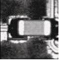
Also known as image-comparison AOI, image-based machines are designed to use the raw information or pixel grid contained in the image. Early systems used gray scale techniques to compare pixel to pixel within a region of interest. In the two images, the same component appears in the same region of interest but with a slightly different angle. Using pixel-by-pixel gray scale comparison, the second image should fail [2], due to lack of information at certain pixel locations within the region of interest. As you can see, this methodology has very poor accuracy when a component is skewed. With new image treatment methodologies, along with increased computing capabilities, image-based technologies have improved. Most systems now employ a bank of images or image library, in order to reference images of known good components as well as known defective components for board inspection (and highlight defective components). Results depend upon quality of the image database which is created from a populated board or boards.
Image-based technologies qualify a component by comparing its image to a collection of known good and bad images. The variety of comparison techniques range from the basic to neuronal networks, but the core question using an image-based AOI is the same: does the current image look like one stored in the image bank? By making its comparison, the machine will either respond with: “Yes, it is a good component,” or “No, I must compare to the next image in the bank.” The comparison process continues until the component is failed or a suitable match is made.
Due to process variability, image-based systems must consult a large, and oftentimes growing, database, which can have an adverse impact on cycle time. Some image-based systems try to compensate for this cycle-time impact by creating models of process variability using a statistical approach with high-speed image acquisition. With this method, the huge image bank is simplified by calculating for each pixel the average and standard deviation of gray level value. During the inspection process, the “distance” between each model and each real component image is used to pronounce a verdict — good or bad. As this AOI captures images of more components and adds them to the image bank, the “statistical” image becomes fuzzier, and the AOI becomes incapable of separating the “good” component from the “bad” one.
Algorithm-based AOI
Using mathematics and geometry, algorithm-based AOI systems employ pattern recognition techniques to locate a component within an image. Instead of comparing one image to another, this technology uses a defined pattern (geometry or skeleton of the object) to find it in the picture.
This is very powerful technology because the component is defined only by its shape, regardless of gray scale or pixel information. Algorithm technology also offers better accuracy because there is no need for pixel matching, and changes in the process environment have no adverse effect. Slight color changes of the component or circuit board do not impact the ability of algorithm-based AOI to identify the component with accuracy. Once this information is saved in the inspection program, the vision system analyzes real-time images to find the pattern in the right location (defined by the component reference designator and X, Y, theta). There are several techniques for doing this, but the most accurate is called vectoral imaging [3]. The vision system highlights the boundaries of the component by a series of vectors. Using mathematical interpolation and sub-pixel resolution, the vectors more closely match the exact shape of the component than the pixel grid. This provides much greater accuracy when matching the component to the library. When inspecting solder joints, lifted leads or bridges, location of the component (component body) is critical and this level of accuracy is required.
Key factors for understanding
How do we translate the differences between image and algorithm-based technologies in metrics that matter to our industry? Given that the first objective of AOI use is to reduce PCB defects, the system must be effective in detecting all defective components at the stage of production where the machine is used. Experience shows, in some circumstances, AOI could miss some defects. This is usually measured by the metric called false accept rate (FAR), expressed in ppm (parts per million) and calculated by the ratio of the number of false accepts to quantity of inspected components.
Often FAR is associated with another metric called false calls rate (FCR), which measures in ppm the number of good components found as defective. The FCR has a direct impact on the process flow and the quality of your process. If the false call rate is too high, the probability of letting real defects escape the system is much higher. Have you ever witnessed an operator performing PCB review, accepting false calls while overlooking a real defect? With a high rate of false calls, this operator is prone to miss the real defect by being lulled by the large number of false calls. The real defect becomes a false accept because the operator was not diligently looking for a defect.
Cycle time also is crucial to the SMT process, and AOI should not be the bottleneck while performing 100% inspection. In some cases, certain AOI machines are required to deactivate some tests in order to achieve cycle time. Most potential AOI buyers use the programming time as a key factor in choosing a machine. Programming includes transforming data from CAD to a working inspection program, then fine-tuning to compensate for variability in the manufacturing process.
Other key factors include program portability and process control, whereby the first is of great importance for users who run multiple PCB assembly lines. When a need arises to move production from, say, line 1 to line 2, it is essential running the same AOI program without time consuming modifications. The second key factor, process control, is critical to customers who not only want to catch defects, but improve the manufacturing process by finding the cause of the defects then correcting. AOI capabilities such as accuracy and repeatability are essential to both of these key factors.
Programming of image-based AOI: Usually, people are introduced to AOI at the programming stage. A great opportunity exists at this stage for discovering the power and capability of the equipment and learning techniques for finding defects and achieving 100% inspection. It is here that the two AOI categories, image-based and algorithm-based, diverge and become two distinct programming methods. The image-based AOI first acquires a bank of images for a program, and programming seems very smooth as the first boards are learned by the machine. But in simply teaching images, the question arises: what did the programmer achieve so far? By capturing images from the first few boards, the machine learns only from a sampling of the lot being tested. When these same boards are inspected a second and third time, the program appears stable and ready for mass production. This teaching process is repeated on other PCBs of different designs and components, and additional programs are created using the small sampling method. To someone unfamiliar with different AOI machines, this programming appears amazingly fast and efficient. When programming a quantity of different products (N), overall programming time appears to be N multiplied by the amount of basic programming time.
Programming of algorithm-based AOI: Programming an algorithm-based AOI greatly differs from those machines that first learn images (can even be programmed offline from data while a PCB still is in the design stage.) Based on mathematical and geometric data for each component and the circuit board used, the machine applies algorithms to inspect each part when board assembly begins. Most of this information is contained in a library, which is linked to the current program and tuned by incorporating current process variation (clear variability affected by the PCB and process). At the first glance, this tuning process is seen as more time-consuming than teaching images on an image-based system, but when programming subsequent products, the same library is used and time spent fine-tuning is recaptured. When comparing programming time from the first product to the last, you can see that when time remains for an image-based AOI, it decreases substantially for the algorithm-based AOI.
False calls and false accepts rates: As previously mentioned regarding programming, image-based AOI appear fast and show impressive results on short production runs while algorithm machines require more time to program. However, as production grows from a few PCBs to just 30 or 40 boards, it is worthwhile to compare these systems further.
False calls and false accepts are the most critical factors when considering AOI machines. Again, catching a defect is the primary function of any AOI. The image-based system, using its bank of images to segregate defective components from good ones, must quickly grow the quantity of images in the bank to allow for process variability. At the same time, this system is very dependent upon the operator who captures these images and feeds the database. This person’s judgment of each flagged component (false call or real defect) is key to growing the image database to allow for variability, and any mistake leads to confusion. In other words, when an operator classifies an image to use it as a reference, he/she mistakenly could reference a defective component as good and vice versa. To be effective, an AOI must eliminate operator error and accurately segregate clearly defective components from good ones. The graph of the criteria for good and defective components (two Gaussian curves), the more detailed and efficient methodology of algorithm-based AOI shows clear discrimination between the two curves, representing stable and reliable results.
Using an image-based AOI associated with an image databank, the risk for unclear criteria is higher because images from good and defective components often appear very similar in appearance to an operator. Moreover, as the operator populates the database, any misjudgment will lead to more confusion: the Gaussian curves become closer and overlapping. The area between the curves represents confusion and generation of false calls and false accepts.
With an algorithm AOI, criteria are established using geometric measurements and thresholds, which produce a clear divide between good and defective components whatever the process variation. This ensures a stable and reliable inspection process for the life of the product.
For the image AOI to maintain the very impressive performance it achieved on a few boards (<50), the core element (the database or criteria) must grow with more and more images as process variation occurs. This blurs the criteria due to the operator judgment factor and leads to poor results on longer production runs (high false call and high false accept rates). On the other hand, algorithm-based AOI with “hard data” programming (based on measurements and threshold) offers a very stable and reliable long-term solution.
Cycle time: The cycle time – loading, inspecting and unloading a board – is driven mainly by the time of all equipment in the line required to produce a specific product of given specifications. In the AOI segment of the line, mathematically reducing pixel size will increase cycle time and most AOI systems must trade away detection of very small features and defects to gain speed. To overcome this issue, some systems are equipped with multiple cameras. There are two camera systems featuring a low and high-resolution capability and correspondingly different FOV. Multiple camera machines selectively inspect very small parts with the higher resolution camera. But implementing a multiple camera machine in production adds cycle time too and limits flexibility.
Another approach is to address the cycle time issue with algorithm technologies to improve resolution without decreasing FOV, which slows the inspection process. With “sub-pixel” technology algorithm AOI improves resolution by a significant factor: there is no time penalty when inspecting small features or components. Additionally, when an assembly process has a lot of variation, cycle time can be a problem for image-based AOI since the machine must check against a growing number of images in the database. The image bank grows in order to maintain an acceptable number of false calls, and it takes more time to process multiple image references for each component. This is one of the most prevalent complaints from users of image-based AOI.
Program portability: This is critical, not only for manufacturers with several SMT lines, but also for smaller shops having only 2 lines. An inability to use the same inspection program on both lines is a huge problem in terms of resources and costs. The users of image AOI face this issue more often than those of algorithm-based machines simply because of this need for images. The AOI camera and lighting in one line would have to be a duplicate of the machine in the other line in order to have program transportability with like images. In other words, a programmer would be required to match images from line to line using two very similar, but slightly different vision systems.
Algorithm-based AOI programs, however, base inspection on measurements of component and circuit board. When these machines are properly calibrated, programs are completely transportable and exchangeable from one AOI to another. This clearly minimizes the cost of ownership by reducing programming and eliminating the need to collect more images.
Process control: More and more users are using AOI to control their process. But to guarantee successful control, the AOI must be accurate and repeatable to provide the best data. Using a bank of images to inspect components cannot provide best results as this method is based only upon what has been inspected previously, and makes no allowances for process variability and excludes precise, detailed definition of what is to be inspected. Moreover, image-based machines just learn “on the fly” with operator input and often require loose tolerances at the inspection stage to lower the false call rate. Process control becomes difficult, if not impossible, to implement with such data. With fast programming and cycle time, image-AOI is very impressive during demonstration or the first days of use. Soon thereafter, users begin to suffer from high false calls, poor defect detection and lack of portability. This clearly impacts quality and adds cost.
On the other hand, algorithm-based AOI measures the component with reference to the CAD data and criteria that are not dependent on any learned characteristics. This system relies on the real component’s geometric shape as defined in CAD, and provides accurate and repeatable data to supply to the process control software. Algorithm machines have been used since 2002 for process and closed-loop control. They remain the system of choice for manufacturers who require rigorous process control parameters for their assembly lines.
Article to be continued in the upcoming issue of EPP Europe. With the focus on ROI (return on investment), comparing image-based and algorithm-based systems in operation over 5 years.
Productronica, Booth A2.417
References
[1] Vi Technology i-LITE construction; Romain Ramel, 2007
[2] Performance Comparison of 2D object recognition techniques; Markus Ulrich, Carsten Steger, ISPRS 2002
[3] Vectoral Imaging: a new direction in automated optical inspection; Mark Norris, 2002
Zusammenfassung
In diesem Grundlagenbeitrag über AOI-Technik vergleichen wir die Vor- und Nachteile von Image- sowie Algorithmen-basierenden Systemen. Wie die Berechnung des Return of Investment (ROI) zeigt, ist trotz höherer Einstandskosten die Algorithmen-AOI über eine längere Nutzungszeit die Lösung, die erhebliche Kostenvorteile bringt. Zudem ist mit deren klaren Messergebnissen auch wesentlich effizientere Prozesskontrolle sowie Qualitätssicherung möglich.
Dans cet article fondamental sur la technologie AOI, nous comparons les avantages et les inconvénients des systèmes à base d’images et d‘algorithmes. Comme le montre le calcul du retour sur investissement, les algorithmes sur lesquels reposent l’AOI sont la solution à plus long terme d’utilisation malgré des coûts de revient plus élevés car ils apportent des avantages de coûts considérables. De plus, leurs résultats de mesure clairs permettent une plus grande efficacité dans le contrôle des processus et l’assurance qualité.
Share:


