
LEDs suffer heat problems limiting their success as a light source. Much attention is given to the heatsink, less to the layers and barriers between LED and the heat dissipating surface. A change of concept and material allows significant gains in thermal management and reliability as well as a simplified system.
Dr. Armin Veitl, Director Design Europe, Altair Engineering
Using ceramics as heatsink, circuit carrier and part of the product design needs some fresh thinking and the willingness to overcome traditional patterns. A simulation method based on Computational Fluid Dynamics supports thermal optimization and technical product design. The paper explains the theoretical approach, the proof of concept and what and how improvement with ceramic heatsinks can be achieved.
LEDs are known to be efficient and are loved for being tiny. But they are only really tiny as long as heat management is not involved. Incandescent light sources work with temperatures up to 2.500°C. LEDs are much colder and many people stumble upon the fact that heat is such an issue. Being relatively cold LEDs still do produce heat which is not yet a problem. But they are based on semiconductors which, roughly speaking, simply allow temperatures below 100°C. According to the law of energy conservation the thermal energy must be transferred to the surrounding area. The LED can only use a small temperature gap between 100°C of the hot spot and 25°C ambience temperature; offering just 75 Kelvin. Consequently a larger surface and powerful thermal management are needed.
Two Optimization Blocks
Group 1 is the LED itself and mainly remains untouchable. Its centre is a die and a heat slug, a copper part, which connects the die with the bottom of the LED. Thermally, the ideal solution is direct bonding of the die to the heatsink itself. Due to mass production this concept is commercially unrealistic. We consider the LED as a standardized “catalogue” product which can not be modified. It is a black box.
Group 2 is the heatsink, transmitting energy from a heat source to a heat drain. This is usually the surrounding air either with free or forced convection. The less aesthetic the material, the higher is the need to hide it. The more you hide it the less efficient is the cooling. Alternatively, pleasing and worthy materials can be used, directly exposed to the air and being part of the visible product design.
In-between group one and two is Group 3 providing mechanical connection, electrical isolation and thermal transmittance. That seems contradictory since most materials with good thermal conductivity conduct as well electricity. Vice versa almost every electrical isolation material translates into a thermal barrier. The best compromise is soldering the LED to a PCB which is glued on the metal heatsink. The original function of a PCB as a circuit board can be kept. Although PCBs exist with various thermal conductivities they remain an obstacle to thermal transfer.
Ceramic: Two Jobs in One Material
It is common to optimize only the heatsink. Hundreds of designs are available, essentially of aluminum. But for further improvement it is necessary to advance or even eliminate the third group! Electrical isolation has to come from the heatsink itself by the use of other materials. Our conclusion is ceramic. Ceramics, e.g. Rubalit (Al2O3) or Alunit (AlN), combine two crucial characteristics: They are electrically isolating and thermally conductive.
Rubalit has a lower, Alunit a slightly higher conductivity than aluminum. On the other hand Rubalit is less expensive than Alunit. Their thermal expansion coefficient is adapted to semiconductors, they are rigid, corrosion-resistant and RoHs compliant. Completely inert, they are the last part of a system to die…The simplified construction (without glues, insulation layers, etc.) combined with a direct and permanent bond between the high-power LED and the ceramic heatsink create ideal operating conditions for the entire assembly. Put simply: What isn’t there won’t wear out and materials that expand in proportion to each other won’t separate. The result is excellent long-term stability, secure thermal management and exceptional reliability. A patent has been filed and the concept has been baptized CeramCool.
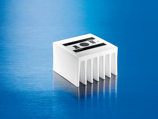
The ceramic heatsink CeramCool is an effective combination of circuit board and heatsink for the reliable cooling of thermally sensitive components and circuits. It enables the direct and permanent connection of components. Also, ceramic is electrically insulating per se and can provide bonding surfaces by using metallization pads. Customer-specific conductor track structures can be provided, if required even three-dimensional. For power electronic applications direct copper bonding is possible. The heatsink becomes a module substrate that can be densely populated with LEDs and other components. It quickly dissipates the generated heat without creating any barriers.
The idea to use ceramics was cross-checked in several simulation models. To predict thermal behaviour of various designs a method based on CFD was developed. As well an optimized ceramic heatsink for 4W cooling was developed. Manufacturing requirements were taken into account. The optimized geometry allows operation of a 4W LED at a maximum temperature below 60°C. The design is square in shape (38mm x 38mm x 24mm) and comprises longer, thinner fins with larger spacing. The identical geometry in aluminum with a PCB mounted LED showed significant higher temperatures. Depending on the thermal conductivity of the PCB the temperature raised between 6 to 28K.
New concepts under developement
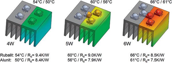
Already a 6K reduction at the hot-spot implies significantly less stress for the LED. The total thermal resistance of the Rubalit assembly is at least 13% better than aluminum with identical shape. Using Alunit the minimum improvement of CeramCool reaches 31%. These good results are outperformed largely for both ceramics if the heat drop of 28K is taken into account.
The concept is flexible and can be used for different targets. It’s your choice whether you run a LED on its optimum temperature assuring high life time and high lumen per Watt or you accept higher temperatures reducing life time and efficiency. A temperature spread from 50°C to 110°C is common. If more lumina are needed the 4W-heatsink can be equipped with 5W or 6W LEDs. Splitting the power into several 1W LEDs helps to get a better heat spreading. The results are 65°C with 5W and 70°C with 6W.
With the chip permanently and reliably bonded to the electrically insulating CeramCool, the heatsink takes more heat and becomes hotter. It takes the burden off the LED and does exactly what it is made to do, namely, cool the critical components. The reduced die temperature allows a downsized surface, a smaller heatsink. Its higher temperature makes it possible.
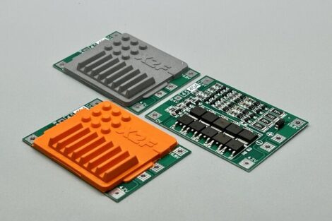
Since most of the applications where CeramCool is used are customer specific solutions, it is essential that the performance can be proved before first expensive prototypes are made. Intensive studies were made to build up simulation models. These simulation models have been verified against various tests and showed reliable correlations to test results. Based on this knowledge, new concepts or variations are easily evaluated. What is the thermal advantage of splitting a 5W LED into 5 LEDs of 1W? What is the benefit of a heat spreader included in the circuit layout?
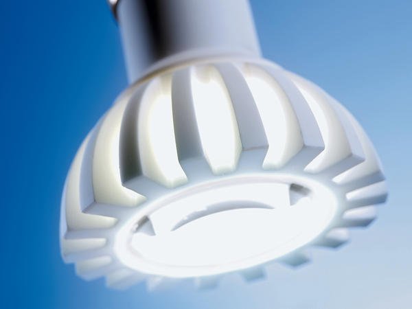
The new CeramCool GU10 LED spot works with any LED. Socket and reflector are made from a single material: a high-performance ceramic. Thus its simple class II construction with safe insulation. A high voltage 4W LED only reaches a maximum temperature below 60°C, so both lifetime and light output are increased. In all CeramCool ceramic heatsinks the substrate becomes the heatsink. Here it acts as the lamp, or even the luminaire. The simplified design delivers extremely high reliability. In addition, the mount and reflector of GU10 LED spots are usually made of different materials. With this solution far fewer materials are used and ceramics are exploited for their electrical insulation, good EMC and high mechanical and chemical stability. Last but not least: The indirect light and the continuous ceramic construction are beautiful.
Share:


