Since its release in 1990, the IEEE JTAG standard has driven the development of many easy to use and highly automated tools for boundary scan testing.These have been recently joined by new-generation low cost or even free test utilities. Boundary Scan itself has also expanded from test use into in-system programming of Flash memories, PLDs and embedded Flash, as well as wide use in debugging interfaces for MCPs, DSPs and SoCs.
Peter van den Eijnden, JTAG Technologies, Eindhoven (The Netherlands)
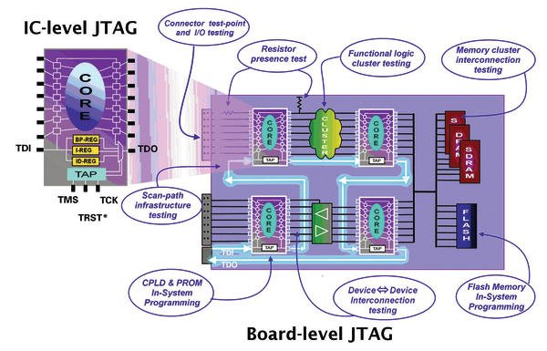
An IEEE 1149.1 – or Jtag – compliant device contains additional logic and a Jtag interface to access this logic. The device’s digital pins each have a boundary scan cell or cells, which are transparent during normal operation. These cells together form the boundary scan register (BSR). In normal operational mode the core function of the device controls the pins of the chip. In test mode the boundary scan register takes over the control of these pins and the individual bits of the boundary scan register are used to drive and sense the device pins independently of the core of the chip. Besides the BSR the device will also have the bypass- and instruction-register, and optionally any number of additional data registers such as an ID-register, for example.
The boundary scan register logic for digital device pins is defined in IEEE Std. 1149.1 (dot 1). IEEE Std. 1149.4 (dot 4), which is in addition to dot 1 and was released in 1999, describes the boundary scan logic for analog pins in mixed-signal devices. High-speed digital pins in advanced digital networks (capacitor-coupled connections) require further additional logic (pulse generator at the driver and an edge detector at the sensor) and is defined in another addition to dot 1 released in 2003, IEEE Std. 1149.6 (dot 6).
JTAG for general test and flash programming
For test purposes the boundary scan register and the instruction set has proved more than sufficient over the years, providing an effective and low cost means to test often inaccessible circuit tracks and components. Boundary scan registers facilitate structural testing of boards providing known fault coverage and immediate diagnosis down to the pin level. Tests like: continuity checks, structural interconnect test, (functional) cluster test and memory interconnect test are easily possible. To simplify the testing of their interconnects future me- mory devices may contain special test logic defined in a new standard released earlier this year: IEEE Std. 1581 for Static Component Interconnection Test Protocol and Architecture.
Thoughtful use of test access provided by boundary-scan has also enabled users to create flash in-system programming applications for NOR and NAND flash memory types and also serial PROMs such as I2C and SPI with relative ease.
Programmable logic devices
Modern programmable logic devices such as cPLDs and FPGAs are equipped with a Jtag interface supporting JTAG programming. Programmable logic vendors such as Altera, Cypress, Lattice and Xilinx were all early adopters of Jtag Technology but not always in order to use its test features. The attraction of boundary-scan for these silicon vendors was a programmer interface that allowed register access to program the macrocell and gate fuse maps.
Of course early on, each vendor devised its own schemes and instructions to implement this. However, by the late 1990s, a common PLD programming standard working group was established. With input from test system developers such as the company as well as the aforementioned cPLD vendors a new standard, IEEE Std. 1532 for In-System Configuration of Programmable Devices, was approved in 2000. This standard specifies a minimum set of data registers and programming instructions that define a standard methodology for configuring programmable devices through the Jtag port. It also specifies an extension to BSDL facilitating standardized automation tools for device programming.
JTAG in Micros and SoCs
Just as PLD vendors used and built on the capabilities of boundary-scan, so too did microprocessor vendors who also fitted basic boundary-scan functionality, allowing structural board tests to be performed prior to board-level and system-level functional tests. However, whereas the PLD vendors focussed on adding functions for ISP, microprocessor vendors added emulator and debugging functions providing the ability to load, run, halt, and step the CPU thus enabling the software engineer to debug CPU code via the Jtag interface. The debug logic can also be used for emulative testing of the processor kernel of a board.
Initially Jtag could only be found on larger, top end 32 bit (now 64 bit) MCPs and a few 16 bit MCUs. However, many silicon companies are now implementing boundary scan across the board. Si labs, for example has an 8051 derivative MCU device. The C8051-F120, with full boundary scan and on-board Jtag debugging plus embedded flash, can also be programmed by register access from the Jtag port. This, along with analog inputs and DIO ports, all comes in a 64 pin package.
For devices like microprocessors it may be desirable to control the power consumption of the debug logic, or to quickly access a specific IP block on a System-on-Chip device to improve the software debugging performance. This additional functionality is defined in the recently introduced IEEE Std. 1149.7 and can be accessed through the Jtag port, or alternatively through a reduced pin-count ‘2-wire’ TAP defined in dot 7. The official name for dot 7 is IEEE Standard for Reduced-Pin and Enhanced-Functionality Test Access Port and Boundary Scan Architecture. The standard was released in 2009 and complements the dot 1 standard with which it is backwards compatible.
Besides microprocessor debug logic other types of instrumentation is built-in into devices for (chip internal) test and measurement purposes. Another additional and associated standard, IEEE P1687 (IJtag), Standard for Access and Control of Instrumentation Embedded within a Semiconductor Device, is now under development. It will describe the methodology for access to the embedded test instruments through the Jtag port, and will provide a standardized description format how to operate the instruments to facilitate their use and re-use at board and system level in a standardi-zed way. Like others mentioned this standard is an extension to the original 1149.1 standard.
Tools for all budgets
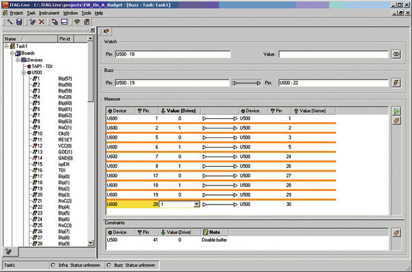
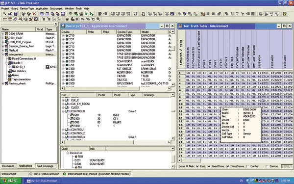
With the increasing availability of IEEE 1149.1 compliant devices in evidence, more and more engineers are harnessing the power of Jtag and formalising test techniques for the first time. There is now an array of supporting products to choose from, ranging from free license, downloadable utilities such as Jtag Live Buzz for interactive pin-to-pin continuity testing, to full blown automated test and ISP application development suites such as Jtag ProVision. Which ever type of tool you choose however, it is important to consider what affect running the boundary-scan tests will have on the non-boundary-scan parts of a design
In the case of low-cost and free tools, it is the engineer’s responsibility to determine the safe conditions under which the boundary scan driver can be activated, so as not to cause contention with non boundary scan device drivers. This is often accomplished by setting pin states that control reset pins or chip enables in a constraints section of the tool.
More advanced tools such as ProVision can automatically generate a full range of boundary-scan applications (including 1149.6 LVDS connection tests and 1532 in-system configurations). What’s more since models are provided to fully describe non boundary scan compliant parts, creating safe test conditions is fully automated and offering a significant advantage to engineers as it saves time and de-risks the tests. In addition to boundary scan software development tools, the associated hardware has come a long way since the introduction of the standard. Controllers with multiple TAPs enable engineers to design circuit boards with more than one boundary scan chain, thus giving the option for a dedicated chain for faster flash programming, for example. Additional tester TAPs also make through connector testing simpler using an auxiliary digital I/O scan hardware module, accessing the board edge and/or test points. Such modules contain Jtag compliant parts that synchronise with those on the board, and their use can lead to near 100% test coverage.
Boundary scan is playing an increasingly important role throughout products’ lifecycles. Jtag can contribute to prototype debugging, manufacturing process tuning or field service repair and firmware upgrades. As the technology reaches all levels of circuit board complexity more engineers will benefit from this invaluable test and programming technique.
Zusammenfassung
Der Artikel zeigt, dass Boundary Scan sich nicht nur zum Testen, sondern auch sehr wohl zur Programmierung sowie Debugging eignet. Dabei werden verschiedene, hoch automatisierte Tools erläutert, um die zunehmenden Bedeutung von Boundary Scan für die Lebenszeit eines Produktes aufzuzeigen.
L’article montre que le Boundary Scan n’est pas uniquement adapté pour les tests, mais aussi très bien pour la programmation ainsi que pour le debugging. A cette occasion, on explique différents outils hautement automatisés afin de mettre en avant la signification croissante du Boundary Scan pour la durée de vie d’un produit.
Share:


