A number of trends in printed circuit board (PCB) assembly demand a wider process window in selective soldering. We have the “traditional” technology production drivers such as the move towards more SMDs (surface mount devices), the miniaturization/smaller distances or the higher lead-free solder temperatures of an improved process window. Now, in addition, there is also the continuous pressure to reduce costs by using cheap/minor quality solder materials, requiring a modified, more robust process that is less sensitive for quality changes. In this article we explain how tools can increase the process window of both single point and multi-wave selective soldering.
Gerjan Diepstraten, Vitronics Soltec BV, Oosterhout, NL
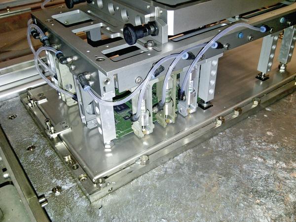
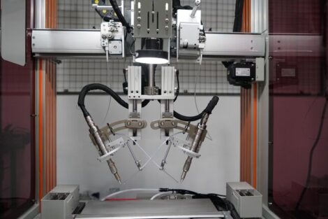
In selective soldering multiple techniques are being used to create the solder joint. The most common soldering method is to have a small nozzle and drag the assembly over the wave. This single point soldering is a robust method, but it is time consuming and creates longer cycle times. A new solder unit that rotates the solder nozzle has been introduced to be more efficient. To gain time, the robot gripper is integrated in the conveyor system. This makes changing more flexible because the gripper doesn’t require board-specific modification, because as part of the conveyor the width is changed automatically and pick up time is eliminated.
For high volume assemblies the dip soldering on a nozzle plate that is specific for each PCB design is the most efficient method with respect to cycle time. In one single dip all solder connections are made. The handling of the board defines the overall cycle time. However, dip soldering is sensitive to bridging since there is no flowing solder. To widen this process a redesign of the solder pot including improved nitrogen performance has been made.
High frequency fluxer
A robust soldering process starts with a well-defined amount of flux on the spot where solder meets the board. The flux has to clean the board, remove oxides and improve the wetting. Reliability in the field also depends on the flux residues. Therefore it is critical that the flux spread and flux amount is controlled. A newly developed high-frequency fluxer is able to apply more droplets per second. The smaller droplets will spread less and are applied more accurately. The nozzle itself weighs only 2 grams and has an internal volume of 35 micro liters of flux.
The target is to have a highly accurate flux deposition with a defined spreading. A very sensitive liquid flow measurement guarantees a controlled flux amount per connector. The low flux flow can be measured using a device that contains a heating element that registers every temperature change which is directly related to the flow rate of the flux.
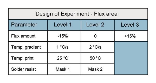
DoE to define flux spreading
The objective of this design of experiment (DoE) is to define these parameters that affect spreading of the flux. Once the mechanism of spread was understood, a second test was done to define a mathematical formula to calculate the spread. The parameters that were selected included the solder mask, PCB temperature during fluxing and preheating gradient. The assembly temperature influences the spreading of the applied flux. When the board is hot, for an alcohol flux the spread will be reduced while for a water based flux the spreading will increase. In this experiment we used a low VOC (volatile organic components) flux, i.e. a blend of two solvents alcohol and water that contained 20% water.
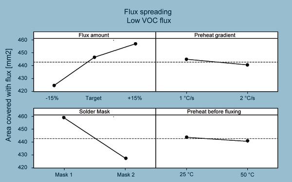
The flux was applied on the board using the mentioned settings. After preheating, the board was taken out of the selective solder machine and the components were removed. The board was scanned and the spreading could be defined using a software program to measure the fluxed area on the scan.
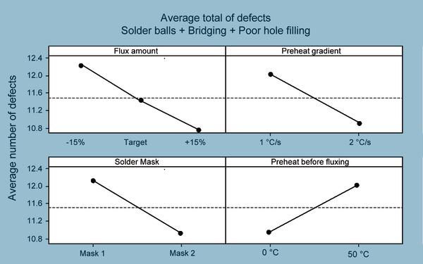
For the same conditions, boards were soldered to verify the solder quality at given settings. The target was to achieve good solder performance with the lowest amount of flux. More flux gives better soldering, the solder mask has significant impact where a faster preheating is preferred, and fluxing a hot board doesn’t return acceptable soldering results, as the figure shows.
For a defined combination of flux and solder mask, it is possible to provide a mathematical formula for the spreading. The surface tension of the solder mask is an important factor. Therefore, there is no generic stand-alone flux formula – rather flux type and solder mask type need always to be considered in combination. This formula can be imported to the external software package to program the selective solder machine off-line.
Soldering fine pitch on select nozzle
If the small nozzle is used and the assembly is dragged over the wave, there are four possible soldering method alternatives. First, one can solder with a wettable or non-wettable nozzle. Second, soldering can happen with the PCB horizontal or under an angle. Soldering with a wettable nozzle under an angle is not common and only used for special application with space limitations.
Bridging is the most critical defect when soldering fine-pitch components. The short lead length and fine-pitch dimensions increase the risk for bridging. The next experiment shows the sensitivity for bridging with a single-point soldering process. The tests are done on a non-wettable nozzle with the board horizontal. This method is used because it has a lead length limitation. The nozzle has an outside diameter of 6 mm. The solder direction is defined by the component orientation. The U-turn of the robot has to be used to turn the PCB 90 degree and solder in the Y-direction. In the next generation solder pot the small non-wettable nozzle will rotate. This way, the robot gripper is only moving in X- or Y-direction without rotation, being faster and more accurate.
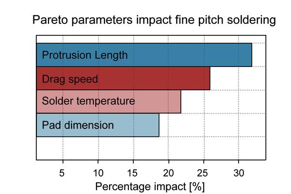
Let’s have a look at the conclusions from the experiment. The fine-pitch components are very sensitive for bridging, as expected. The lead protrusion length is a significant factor on fine-pitch bridging. A small lead length gives much less bridges. For usual 1.27mm pitch components the best results are achieved with 0 to 0.1mm lead-length. Standard IPC-A-610E requires that the lead is discernible at the solder side of the joint. This might be a point of discussion for fine-pitch components with short lead length, since the solder might have a concave shape. The higher solder temperature gives a better drainage and solder doesn’t solidify that fast which helps to limit bridging. By employing the right methods, soldering 1.27mm pitch pin connectors is feasible and already applied at some of the selective soldering lines in the field.
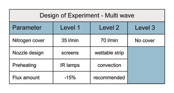
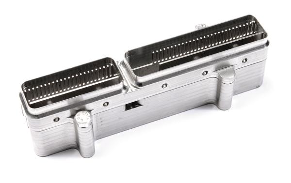
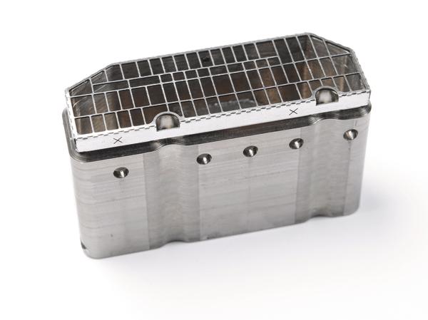
Soldering fine pitch on a multi-wave plate
Critical defects in the multi-wave dip process are bridging and solder balling. Both defects are closely related to the nitrogen environment at the soldering area. A new cover option has been introduced that keeps oxygen levels below 100 ppm during the soldering. However, such a low ppm level alone will not eliminate bridging. To achieve high yields two additional options are introduced:
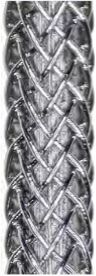
- Wettable strips in nozzles
- Non-wettable laser-cut stencils on top of the nozzle
An experiment was done to gather a better understanding of how to eliminate bridges in this process. In this experiment a forced convection heater is installed to compare with the traditional IR heaters.
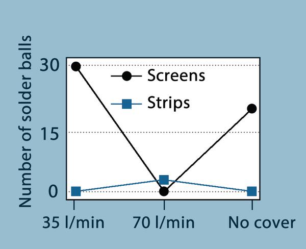
This test is applied on a multimedia board from an automotive supplier who runs this assembly in a high-volume production line. Overall soldering performance was good – only limited solder balls were observed. Bridging could only be seen when the nitrogen cover was not installed.
The data shows that nitrogen has a big impact on the process and that lower oxygen levels generate less solder balls. This is in contrast with previous findings in wave soldering processes which showed that the solder mask has the most impact on solder balling. Based on our tests, the most likely conclusion is that nitrogen improves the flowing properties of the solder and the flux activity, therefore limiting creation of solder balls.
The convection heater brings more equal divided heat in the assembly, improving soldering and limiting solder balls. The process is optimized then, and solder balling is kept to a minimum when the test board is preheated with the convection unit and soldered with a nitrogen cover.
The results indicate that wettable strips generate the lowest solder balls compared to soldering with nozzles only or nozzles with non-wettable stencils. However, the interaction between the non-wettable stencils and nitrogen is a significant factor. Stencils require a certain inert atmosphere, and this is achieved with the nitrogen cover and 70 l/min. Under these conditions the stencil renders a very stable process with minimum defects. This is confirmed by the data from users. For lower nitrogen consumption there is a risk that a small oxide film will show up on the solder. This oxide film may impact the performance of the stencil.
Let’s again have a short look at the conclusions from the above experiment. The nitrogen cover definitely opens the process window for the multi-wave dip soldering process. All soldered boards showed 100% through-hole filling and as such are reliably meeting the IPC-J-STD-610E criteria for class 3. Adding non-wettable stencils or wettable strips to the nozzles also eliminates bridging defects. If the nitrogen cover is not used, the wettable strips are still able to solder without bridging, but the non-wettable stencils are not.
Field introduction
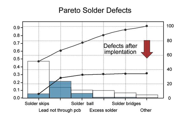
The nitrogen cover system has been introduced in the field at different customers. The graph shows that selective soldering defects decrease dramatically, and at the same time the small window of the dip soldering process is opened significantly wider. Not only did bridging decrease, but the rate of other defects associated with flux activity also declined, just like skips and solder excess.
Productronica, Booth A4.135
Zusammenfassung
Die Aufgabenstellung beim Selektivlöten ist nun entschieden gekennzeichnet von Minimierungen der Prozessdefekte wie Brückenbildung oder Lotperlen, und der gleichzeitigen Verwendung von kostengünstigeren Loten. Ein breiteres Prozessfenster ist dafür unbedingt nötig. Eine Lösung mit rotierendem Nozzledesign und verbesserter Stickstoffführung reduziert merklich die Fehler und ermöglicht eine größere Verarbeitungsbandbreite der bleifreien Lote.
La mission lors de la soudure sélective est désormais décidée et caractérisée par la minimisation des défauts de processus tels que les formations de pontages ou les bosses de soudure et par l’utilisation simultanée de soudures à prix plus attractif. Une large fenêtre de processus est absolument nécessaire pour cela. Une solution avec un design d’embout rotatif et une meilleure alimentation en azote réduit considérablement les défauts et permet une plus grande plage de traitement de la soudure sans plomb.
Share:


