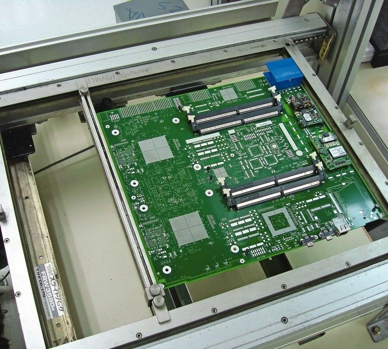
Numerous high thermal mass components place demands on the selective soldering process, while the use of specialized fixtures and pallets often places an additional thermal demand on the preheating process. Fine-pitch through-hole components and connectors place a different set of demands on the selective soldering process and require special attention to lead projection and traverse speed to minimize bridging between adjacent pins.
Dual in-line memory module (DIMM) connectors, compact peripheral component interface (cPCI) connectors, coax connectors and other high thermal mass components as well as fine-pitch micro-connectors can present challenges when soldered into backplanes or multilayer printed circuit board assemblies. Adding to this challenge, cPCI connectors can present additional solderability issues due to their beryllium copper termination pins.
Choosing a flux
Liquid fluxes for selective soldering are available in many types including alcohol-based fluxes, water-soluble fluxes, rosin-based fluxes, low pH fluxes and fluxes with high solids content. The selection of a particular type is generally specified for the end application of the product and is critical regarding the resulting solder joint integrity.
Flux chemistry selection criteria should be based on the solderability of the base metal surfaces being soldered. Base metals that are easy to solder, including platinum gold, copper, tin-silver or palladium silver, can typically be soldered with either a no-clean flux, a non-activated rosin flux or a mildly activated rosin flux. Ones that are not as easy to solder, such as beryllium copper, require either a fully activated rosin flux, a water-soluble organic flux or a water-soluble inorganic flux, with these latter flux types requiring post-soldering cleaning of the board assembly.
Process control essentials
It is known that liquid flux must be present and active in order to clean and protect solderable surfaces before they encounter liquidous solder flowing from a selective soldering nozzle. Since the function of a liquid flux is to raise the energy level and promote wetting of the solderable surfaces, proper thermal activation is essential to dry the flux vehicle and activate the flux solids. High melting point solder alloys require robust fluxes capable of surviving higher preheating temperatures needed for these specialty high melting point alloys.
Preheating is required to ensure proper thermal activation of a given liquid flux chemistry with the thermal aspects of flux activation, such that the topside temperature of a PCB at the end of the preheating cycle is generally specified for proper condition of specific flux type. The total heat cycle consists of the preheat time and temperature as well as the dwell and contact time with the liquidous solder. This time-temperature profile is affected by the thermal mass differential of the PCB assembly, as well as the rate of heat dissipation of high thermal mass components or fixtures and/or solder pallets.
When selective soldering high thermal mass board assemblies, the solder nozzle alone is not always a sufficient heat source to overcome the thermal mass of large through-hole component leads without preheating the board. Topside and bottom-side preheating in combination with sustained preheating may be required for boards with high thermal mass through-hole components in order to achieve Class 3 topside fillets.
Flux migration often occurs since flux spread is influenced by the surface tension and temperature of the board. Alcohol-based fluxes have a lower surface tension than water-based fluxes while water-based fluxes spread more rapidly as alcohol-based fluxes tend to dry faster. While drop-jet fluxing produces a narrow spray pattern compared to aerosol spray heads with minimal deflection of flux droplets, flux satellites can occur and should be mitigated. They will not be directly exposed to liquidous solder and can result in iconic contamination and potential electro-migration issues, if the board assembly has to function in a high humidity product environment.
Design considerations
Design for manufacturing and assembly (DFMA) is defined as designing a product to be produced in the most efficient manner possible in terms of cost, resources, and time, taking into consideration how the product will be processed, utilizing the existing skill base and minimizing the learning curve, to achieve the highest yields attainable.
DFMA is a major concern since many PCB assemblies are designed by those who have little manufacturing experience. This is especially true for original equipment manufacturers who operate in a virtual manufacturing business model, designing, marketing and selling electronic products while outsourcing the manufacturing to external parties.
With respect to selective soldering of challenging through-hole components, it is recommended that design guideline attention be given to adjacent component clearance, lead-to-hole aspect ratio, lead projection and thermal reliefs. Adjacent component clearance, or the distance between a though-hole pad and an adjacent SMT pad, is key since under most conditions it is essential the selective soldering nozzle be allowed to over-travel the last rows of component pins to prevent bridging.
Proper consideration should be given to lead-to-hole aspect ratio to ensure complete vertical hole fill of through-hole components. An accepted best practice allows for a maximum aspect ratio of 1.5:1.0 of the plated through-hole (PTH) diameter verses the component pin diameter. It is also imperative that consideration be given to component lead projection to prevent bridging between adjacent though-hole solder joints. The maximum lead projection should be equal to, or less than, one-half the pitch between adjacent through-hole components leads.
Thermal relief design elements should also be incorporated into PCBs, whenever high thermal mass through-hole components in combination with heavy ground planes are employed. Recommended thermal relief design guidelines should include: inside diameter = drilled hole size plus 2x annular ring, outside diameter = inside diameter plus 0.5 mm, spoke width = 0.02 mm minimum, 0.4 mm preferred, and rotate thermal reliefs of alternate layers in multilayer boards by 45 degrees to minimize internal board stress in the Z-axis direction.
Challenging components
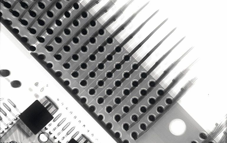
Among the many different types of challenging components are 1.0mm pitch staggered row dual in-line memory module (DIMM) connectors, particularly when soldered into multilayer PCBs with heavy ground planes. Attention should be given to lead projection and solder nozzle traverse speed to minimize solder bridging of these connectors.
Another challenging component is the 2.0 mm pitch six row compact peripheral component interface (cPCI) connector that requires special attention due to the solderability issues of its beryllium copper base metal and gold-plated pins. Since these connectors are often mounted in high density interface (HDI) boards, or into heavy backplanes, they are often held in place with specialized fixtures or pallets which places an additional thermal demand on the selective soldering preheating process.
Other high thermal mass components, including coax connectors and ceramic pin grid array (PGA) devices commonly used in military and aerospace applications, can place additional demands on the preheating process if sustained preheating is not employed. Fine-pitch through-hole components, such as 1.27 mm and 1.0 mm pitch micro-connectors, place a different set of demands on the selective soldering process and typically require special attention to lead projection and traverse speed to minimize bridging between adjacent pins. Ribbon connectors with a pitch of 1.27 mm, and as fine as 0.5 mm, can be selectively soldered with the assistance of a nitrogen de-bridging knife.
Mitigation of gold embrittlement
Immersion gold over a copper base metal is highly resistant to the effects of corrosion since gold does not oxidize and provides a protective layer with a highly solderable surface that is bondable for both gold and aluminum bonding wires. However, since gold melts at a relatively low temperature, it can result in gold embrittlement when combined with other metals to form a solder joint.
As the gold plating dissolves rapidly during soldering, the remnant gold within a solder joint can weaken the integrity of the interconnection. If this gold dissolution is excessive during the solder alloy’s liquidous phase formation, the composition and mechanical properties of the solder joint will change. Gold embrittlement within tin-lead (SnPb) solder joints is a well-known failure mechanism. Lead-free solder alloys such as SAC305 are more capable of maintaining mechanical properties when combined with gold partially due to its additional tin content, however lead-free solder joints will also degrade with increased gold content.
Beginning with the IPC J-STD-001 Rev F requirements in 2014, and continuing with the current Rev G, it has been stated that gold shall be removed from: at least 95 % of the surfaces to be soldered of through-hole component leads with 2.54 µm or more of gold thickness, from 95 % of all surfaces to be soldered of surface mount components regardless of gold thickness, and from the surfaces to be soldered of solder terminals plated with 2.54 µm or more of gold thickness. With this, gold removal is therefore required for all high-reliability Class 2 and Class 3 electronic products.
The removal of gold plating from component leads can be facilitated by a pre-tinning process which removes the gold as it is solubilized in the molten solder during the re-tinning process. A double tinning process or dynamic solder wave may be used for gold removal prior to soldering the components into a board assembly, as improper removal on leads and terminations prior to board level assembly can result in solder cracks and/or field failures.
Solderability testing
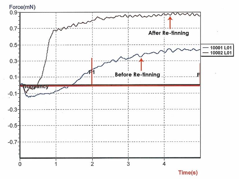
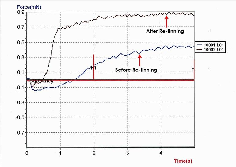
The wetting balance tester, also known as a meniscograph, is an instrument used to access component solderability. This test method uses a strain gage to measure the buoyancy of a component lead when immersed into a bath of molten solder. The resulting force verses time wetting curves measures solderability with component leads having good solderability exhibiting rapid buoyancy, and oxidized or un-solderable leads displaying slow buoyancy, or retarded wetting.
Through-hole and surface mount components that exhibit poor solderability can be reconditioned using a component re-tinning procedure after which a major improvement in solderability can be confirmed, since an improved intermetallic is achieved during the component re-tinning process.
Legacy components used for end-of-life (EOL) product builds, may be decades old having been stored in uncontrolled conditions leaving them generally oxidized with poor solderability, which can result in poor quality solder joints. Refurbishing these components will replace oxidized, plated finishes that are deemed un-solderable with an intermetallic homogeneous finish that is impervious to oxide growth and will mitigate possible tin whisker growth.
Conclusion
Solderability is no longer an option for many high reliability segments of the global electronics assembly industry. With implementation of the recent Rev G of IPC J-STD-001, solderability testing, gold removal and component re-tinning have become prerequisites for doing business and remaining competitive in the global electronics marketplace.
productronica, Booth A2-345
Zusammenfassung
THT-Bauteile können mit dem Selektivlötprozess leicht gelötet werden; einige Arten von anspruchsvollen Bauelementen erfordern jedoch zusätzliche Aufmerksamkeit, um eine optimale Prozesskontrolle zu gewährleisten, wie der Artikel zeigt.
Résumé
Les composants THT peuvent être facilement soudés à l‘aide du procédé de brasage sélectif, mais certains types de composants plus exigeants nécessitent une attention supplémentaire pour assurer un contrôle optimal du processus, comme le montre l‘article.
Резюме
Компоненты для сквозного монтажа в отверстия (THT) можно легко паять с использованием метода селективной пайки, однако некоторые типы особенно чувствительных компонентов требуют дополнительного внимания при осуществлении контроля процесса. Этому и посвящена данная статья.


