Paste-in-hole (PIH) printing, a.k.a. through-hole printing, pin-in-paste, intrusive reflow, etc., has always been a way to accommodate traditional through-hole components on a mixed-technology SMT assembly using reflow soldering rather than wave to make the through-hole connections. Paste is printed in such a manner to as to fill the through-holes, the through-hole components are inserted, and the assembly is reflowed. The shrinking PCB size with fine-pitch SMT pads adjacent to paste-consuming through-holes resulted in deposition issues.
Michael L. Martel, Speedline Technologies, Inc.
Assuming that the TH (trough-hole) components can take the heat of the reflow process, successful PIH boils down to three basic issues:
a) determining the amount of metal needed in the hole to create a good solder joint; b) getting the metal (paste) in there; c) keeping it in there without loss when the the pins of through-hole component are inserted.
Over time, changes in technology have made PIH even trickier. For example, early-on, an important issue was the heat tolerance of the through-hole components subjected to reflow temperatures in an oven. Nowadays, the shrinking real estate of the PCB with fine-pitch SMT pads closely adjacent to paste-hungry through-holes has raised deposition issues, thus affecting design considerations, and the list goes on from there.
How much paste?
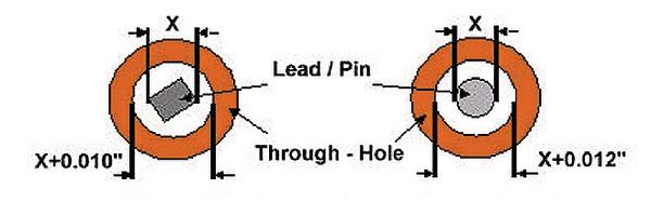
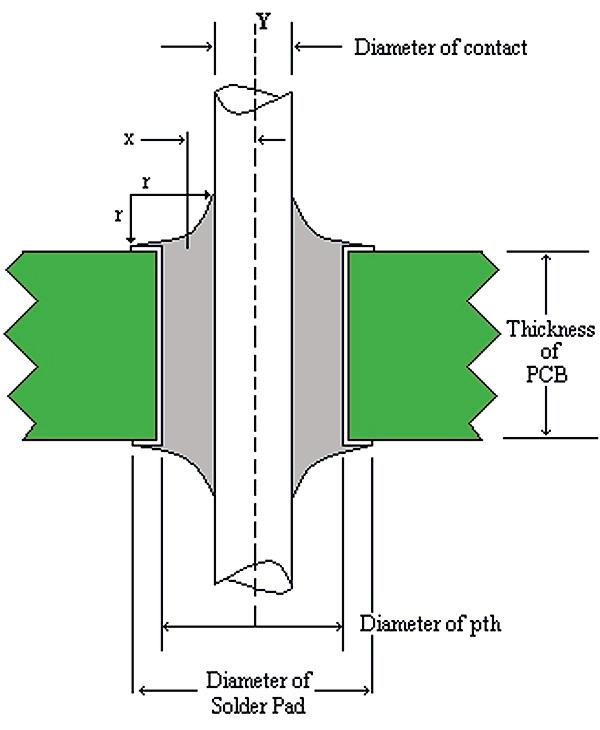
There are as many well-established guidelines for calculating how much actual metal and thus actual solder paste must be deposited or printed in order to properly fill a through hole. Keeping in mind that solder paste is roughly only 50% metal, we know that we must put twice as much solder paste down as calculated to create an acceptable solder joint. The larger the barrel, and the deeper the barrel due to PCB thickness, the more we’ll need. The figure above is a typical example of guidelines for calculating pin-to-barrel tolerances. Board and component designs must be considered first, since some outgassing of the paste will require room, as will placement tolerances for auto-insertion machines. Once these are right, one may calculate the amount of paste required knowing the following characteristics: pin dimension, board thickness, hole size and annular ring size. First calculate the volume of the pin and then the volume of the plated-through-hole (PTH). Subtract the pin volume from the PTH volume. The resulting paste volume must be multiplied x2.
Since paste is generally about 50 to 55% metal by volume, you may need to overprint the pad area to ultimately deliver the calculated volume of solder to the connection. This overprinting is typically 10% on the annular pad; but remember that this is also a function of the connector pitch and spacing available.
Another approach suggests the use of preforms to add pure metal volume to the printed paste where enough paste might not be able to be applied due to PCB design considerations, etc. This has become somewhat popular in some quarters, with the preforms available in tape and reel packaging exactly like chip capacitors and resistors. However, preforms add to the costs and also an extra (placement) step to the process.
Retention
Once the paste is printed, keeping the ideal volume in the hole without loss during pin insertion is not necessarily easy. Although there is no requirement for special paste types, paste formulations do vary, including such attributes as tackiness and viscosity, and this can affect the propensity for paste to be dragged out of the hole by the pin, dripping, etc. The amount of paste dragged out will vary according to a number of factors including changing paste viscosity with temperature change over time, humidity, etc., thus it is not safe to assume that a consistent amount of paste will stick to the pin every time; the amount is paste-dependent. Pin shape is a factor. One suggestion seen has been to use tapered pins for connectors, for example, to minimize the paste volume pushed out of the hole. This will have less of an effect than a pin with a squared-off end that is likely to push the most paste out, which will simply drip off the pin during heating prior to reflow. One innovative suggestion has been to put a bar across the center of the hole (split aperture stencil design, typically about 30% of the diameter) thus forcing the paste down the edges of the barrel and reducing the tendency for push-through. However, be mindful that a smaller (or partially obstructed) barrel will require greater pressure on the solder paste in order to achieve the same level of paste depth penetration as an unobstructed aperture.
Printing and penetration
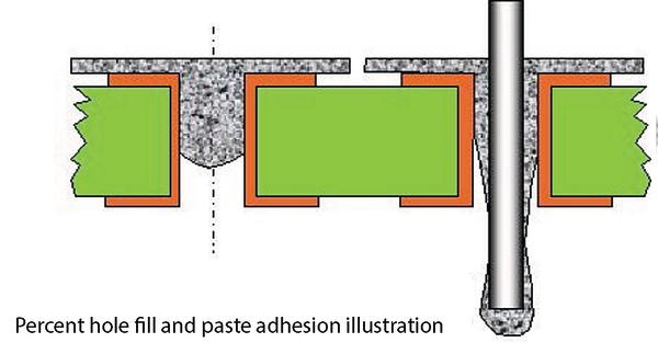
The biggest issue with PIH is of course getting enough metal into the hole. Paste gets into the hole two ways; first, by being printed effectively, and second, by coalescing at the surface in overprinted areas and subsequently wicking down into the hole. A great deal has been written about different approaches to PIH over the last decade, and there are many different formulas and approaches to the successful implementation of the process. But PIH has become tougher with shrinking board topographies because often, high paste volume PIH holes are too close to low-volume requirement fine-pitch SMT pads.
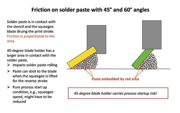
Aperture fill volume percentages are a function of paste pressure, generated by the rolling bead of paste driven across the stencil foil surface by the metal printing blade. More pressure results in better aperture fill for fine pitch, and may be required for more thorough print-filling of PIH holes, but when one has a high paste volume requirement such as an array of through-holes next to fine pitch, the paste pressure in the bead will be reduced by the through-hole requirement and thus rob needed pressure from the fine-pitch apertures, with the result being poor aperture fill. Also, if the board is thicker than 1mm, multiple print stokes may be required, which increases the possibility of paste deposit defects on the fine-pitch pads. Increasing squeegee blade angle has inherent risks primarily based around paste sticking to the blade holder, a real problem in a production setting.
Three different stencil types have been traditionally used in PIH applications: non-stepped stencils, step stencils, and 2-print stencils. Step stencils are expensive and can damage print blades (as well as sustaining damage themselves), and the minimum step-up requirements between step areas (to prevent blade damage) place burdens on the PCB designer. The 2-print stencil technique requires a second printer in-line to perform the 2nd print! Additionally, step stencils create another very significant cost that impacts the overall cost of using them, i.e., reduced throughput and material expense due to the need to increase underwipe frequency. In terms of materials alone, e.g., wasted paste, wiping paper, and toxic disposal of the waste paste residue, it’s a very significant contribution to operating cost.
Overprinting is currently an extremely popular technique, and involves printing solder paste in a masked radius around each PIH hole. However it can be extremely ‘paste hungry’ in certain areas. With the trend (or requirement) to use 100/120µm stencils today, versus the 150µm standard thickness 10 years ago, the need for overprinting is even greater than it used to be. The intent is that the solder will coalesce upon reflow and wick toward the through hole and fill it with sufficient solder. This was a much more reliable technique before Pb-free solders which generally don’t coalesce or wick as nicely as pre-RoHS pastes. Thus, stray solder balls are always a concern as well as wicking to adjacent component leads, causing bridging, and other problems requiring rework.
Enclosed media solution
No single technology solution is a complete answer to all concerns; however, the controlled uniformity of solder paste pressure that is provided by enclosed media printing answers many of them. In many instances it can eliminate the need for step stencils, overprinting, and 2-print methods. It saves considerable material costs and paste waste over step stencil printing. Throughput is increased through less frequent underwiping, which also saves solvent (in solvent systems) and paper.
In an enclosed media system, paste pressure is mechanically controlled and maintained so that aperture fill is optimum even for fine feature device patterns in close proximity to paste-hungry PIH holes. Paste pressure is not dependent on squeegee angle of attack or speed. It is a closed system where paste replenishment in the plenum is automatic via a closed-loop sensor system. Since the pressure can be adjusted, hole fill can be optimized, and other process variables maintained as constant values without the need to tweak. chamber pressure is actively maintained at ±0.1psi from set point.
The only way to affect filling „capability“ of PIH with squeegee blades is through varying print speed and attack angle. However, when using an enclosed media print head, an additional control parameter can be used to affect filling, and this is the ability to set and control chamber pressure, i.e., the pressurization of the solder paste within the enclosed chamber of the print head. As an example, the pressure setting range for a pure SMT board would be 0.1 to 0.12 bar; for a mixed board with PIH, 0.12 to 0.15 bar. Additionally, the ability to vary print speeds within certain areas of the stencil/board provides even greater process setup freedom and flexibility when considering specific areas of the board or pattern that may have more demanding or pattern-specific requirements.
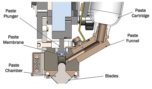
Print head design and operation
The enclosed media print head maintains solder paste in a closed print chamber that is mechanically pressurized to force the solder paste out of the chamber and onto the substrate. Pressurization is accomplished mechanically by a motor-driven plunger or piston that is separated from the paste by a membrane. The plunger applies pressure directly to the volume of paste in the chamber, and a series of transducers sense the pressure and are part of a closed-loop system of very tight pressure control that maintains chamber pressure actively at ±0.1psi from set point.
Conventional squeegee blades are replaced with metal blades that function as both scraper and seal. These blades are aligned in a leading edge configuration at 45 degrees, as opposed to a typical trailing edge squeegee configuration. The inwardly-inclined blades are 10mm apart at the point of contact with the stencil. When the head is lowered onto the stencil, the stencil foil will close the entire print chamber during operation and allow a positive pressure to be generated inside. Silicone dams seal the opposite ends of the chamber. The enclosed media print head differs from similar types of enclosed media in that pressure is applied to the solder paste mechanically, not through air pressure. Air pressure is used to drive the paste out of the cartridges, through a manifold, and into the paste chamber. Pneumatic pressure is employed only to fill the chamber; it plays no role in pressurizing the paste for printing. See figure for a plot of chamber pressure during a simulated production run. Inter-board pressure data illustrates how tight, closed-loop chamber pressure control is maintained consistently board-to-board regardless of paste consumption requirements (large apertures & small).
Conclusion
PIH processes are decidedly more complex than traditional SMT in terms of process control, but with good PCB design and engineering, a properly optimized stencil, and an appropriate enclosed media paste printing/delivery system, it can be a very controllable process. The blade printing process is simply not steady and repeatable; it is constantly changing not only due to the nature of the material being used, i.e., solder paste, but also because the volume of paste on the stencil is never constant. Thus, optimum results depend largely on the skill and discipline of the operator running the printer, and of course this is widely variable. Enclosed print heads eliminate these concerns in regard to line staff.
Productronica, Booth A3.119
Sources
Paste in Hole Printing. Speedline Applications Note, January, 1999
Coleman, William E., Jean, D. and Bradbury, J.. Stencil Design for Mixed-technology Placement and Reflow, SMT Magazine
FCI Corp. CDC-PIPGUIDE-02/07-E, Pin in Paste Application Guide, pp. 2–14
Demirtas, A.: Pin in Paste Stencil design for Notebook Motherboard, Global SMT & Packaging, February, 2008
Willis, Bob, PIHR Technology, Chapters 1 – 11, copyright BR Publishing, Seaside, OR 2012
ZUSAMMENFASSUNG
In der SMT-Baugruppenfertigung müssen zwangsläufig neben SMDs auf dem gleichen Board oft auch bedrahtete Bauelemente mit verarbeitet werden. Problematisch war bisher immer wieder das Aufbringen der Paste und der Lötvorgang für die THT-Komponenten im SMT-Prozess. Speziell die Füllung der Durchkontaktierungen mit Lotpaste für die THTs ist kritisch, denn im herkömmlichen Lotpastendruck ist nicht immer sichergestellt, dass genug Paste in die Kontaktierungsöffnungen gelangt. Mit einem speziellen Druckkopf kann nun komplikationslos der Druck auf die Paste zur Erhöhung des Pastenvolumens beim Einbringen in die Durchkontaktierungen erhöht werden, ohne den Anpressdruck oder Anstellwinkel der Druckrakel zu verändern.
Dans la fabrication d’ensembles de construction SMT, il faut inévitablement conjointement aux SMDs et sur le même tableau souvent traiter des éléments de construction câblés. Ce qui était problématique jusqu’à présent, c’était encore et toujours l’application de la pâte et le processus de soudure pour les composants THT dans la procédure SMT. C’est tout spécialement le remplissage des communications traversantes avec de la pâte à soudure qui est critique pour les THTs, car dans le dépôt de crème à braser habituel, il n’est pas toujours garanti que suffisamment de pâte parviennent dans les ouvertures des contacts. Avec un bouton spécial, il est désormais possible et sans aucune complication, d’augmenter la pression sur la pâte pour augmenter le volume de pâte lors de l’introduction dans les contacts traversants, sans pour autant modifier la pression d’application ou l’angle d’attaque du rebord de pression.
Share:


