Solar cell substrates are delicate. The manual soldering process applies stress to the material which can cause micro-cracks to form. Here, we identify the requirements and equipment needed to reduce the micro-cracking during solar cell assembly, where a couple of cell rows are manually soldered together to create the collector grid. As cell thickness is minimized, soldering has become demanding because these cells are more sensitive to thermally induced micro-cracking.
Paul Wood, Advanced Product Applications Manager, Metcal, Chandlers Ford (UK)
During the manual soldering operation, differential thermal expansion of the copper and the silicon elements can occur at temperatures greater than 300°C. This differential can result in the formation of micro-cracks that may not be detected. There are two soldering process steps used to assemble a PV module; the first step is photovoltaic cell interconnection, called stringing or tabbing, and the second step, PV module assembly, is called bussing.
Initially, the cells are electrically connected using tinned copper ribbon which is typically 2mm wide. The solder-coated ribbon is dipped into, or sprayed with, flux. The flux is used to promote wetting and remove oxides from the surface of the ribbon. A point of contact between the collector grid (substrate) and the ribbon is formed by screen-printing a metallization paste to the substrate. The tabbing ribbon provides all the solder required to form a bond between the ribbon and the substrate.
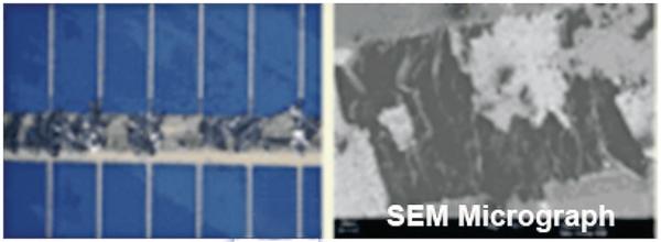
Next, individual PV cells are attached in series forming a column by reflow soldering and precisely placed onto a glass substrate. Six to ten rows of cells are then „bussed“ together using 5mm wide bus ribbon to create the collector grid. Bussing together the columns of solar cells is performed by hand using a soldering iron. The need to reduce PV (photo voltaic) systems manufacturing costs is driving a steady reduction in the thickness of wafers and cells. As a result, the soldering process has become more challenging because the thinner cells are even more sensitive to thermally induced micro-cracking.
During the manual soldering operation, differential thermal expansion of the copper and the silicon elements can occur at temperatures greater than 300°C. This differential can result in the formation of micro-cracks that may not be detected during the manufacturing process and result in a less than expected field lifespan. The need for precise time and temperature control is additionally critical by the intermetallic layer requirement of within 1 to 2µm that must be created during the solder joint formation.
Process control and defect detection
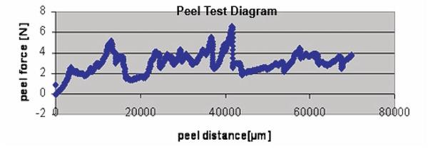
A process window to reduce cell damage and consistently produce good inter-metallic bonds between the ribbon and the solar cells must be identified and maintained. A controlled time and temperature are needed at the solder joint to form an inter-metallic layer of 1 to 2µm. Precise control of time and temperature reduce the possibility of forming micro-cracks in the substrate. Damage to the crystalline silicon can be detected by conducting a peel test according to conventional soldering interconnect joint specifications.
Peel force values up to 6 Newton (1.1 pounds of force), which is within IPC/EIA J-STD-001 for a conventional solder interconnection joint, should not damage the interconnection. After peeling off the ribbons, the tabbing ribbon remains in partial contact with the metallized substrate of the solar cell.
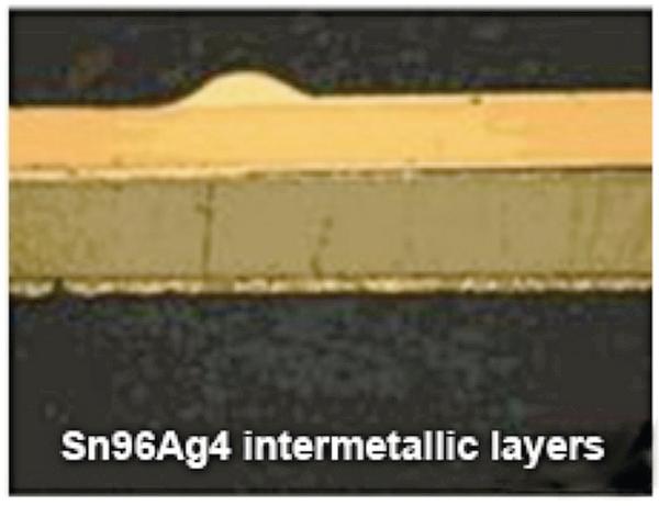
There are two suitable solder alloys utilized for solar cell soldering application. First, Sn96Ag4 with a melting point of 221°C; second the bismuth containing Bi58Sn42 with a melting point of 138°C. Proper soldering will result in an intermetallic layer that is within 1to 2μm. The soldering temperature must be reduced to a minimum so that the solar cells will not be subjected to mechanical or thermal stresses from the hand soldering process
The SmartHeat solution
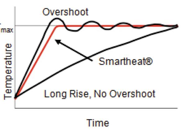
A thermal technology exists that will produce and maintain a specific, self-regulated temperature with a heater that requires no calibration and responds directly to thermal loads. The proprietary SmartHeat technology consists of a high frequency alternating current (AC) power supply and a self regulating heating element. The heater utilizes the electrical and metallurgical characteristics of two different metals: one is copper, which is a material with high electrical conductivity, and a magnetic material with high resistivity. When the heating element is energized by the high frequency alternating current (AC) power source, the current will automatically begin to flow thru the conductive copper core of the heater. However, as the AC current continues to flow, a physical phenomenon known as the skin effect, occurs and the current flow is directed to the skin of the heater assembly, driving the majority of the current thru the high resistance magnetic layer and causing rapid heating. As the outer layer reaches a particular temperature (which is controlled by its heater alloy formula) it loses its magnetic properties. This Curie point temperature is when the skin effect begins to decrease, again permitting the current back into the conductive core of the heater and repeating the cycle.
SmartHeat technology is thus an inherently temperature stable form of resistance heating. Because of this inherent stability, it eliminates the need for external temperature control devices, and is characterized by:
- Temperature self-regulation
- No temperature overshoot
- Fast thermal response and recovery
- High watt density direct power
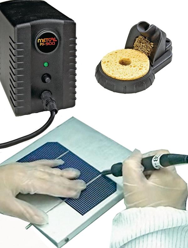
Experiments were performed using the Metcal SmartHeat PS-900 soldering system to evaluate its suitability for solar cell applications. Custom designed STV-DRH440A hoof tip geometry was chosen to optimize the power delivered to the solder joint, thus providing high performance efficiency with increased tip life. The temperature-sensitive T-heater series was chosen to ensure low temperature soldering and thus to minimize thermally induced stresses on the surface of the solar cells. In order to minimize thermally induced damages of the solar cells due to micro cracking, it is critical to maintain the solder joint below 300ºC at all times during the soldering operation. This was demonstrated by using the PS-900 system with the STV-DRH440A tip to solder a twelve inch strip of 0.4 mm ribbon onto the surface of a solar cell. The solder ribbon was placed on top of five thermocouples positioned three inches apart and the heated soldering tip was moved along the surface of the ribbon. Results show that by moving the heated soldering tip at an approximate rate of 25mm/s (one inch per second), solder reflows efficiently at the ribbon and results in the formation of an intermetallic bond of within 1 to 2µm. Moreover, since the heat is delivered directly to the solder joint, the temperature profile measured at the ribbon is observed to be uniform and follows a repeatable curve below 300C with no thermal overshoot. The quick response of the SmartHeat PS-900 system combined with the lower T-series tip temperatures helps minimize the thermal gradients and thus maintains high yields and module reliability for the solar cell application. In conclusion, a variable output power supply combined with a soldering tip designed specifically for the application will measurably reduce the potential for cell damage. By applying only the thermal energy required to form a good intermetallic bond between the ribbon and the solar cell, the SmartHeat system will operate within a much smaller and safe process window.
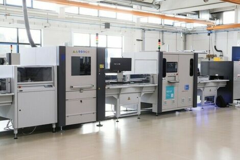
Productronica, Booth A4.221
zusammenfassung
Bei der Assemblierung von Solarzellen werden die einzelnen Reihen manuell per Lötkolben verbunden. Die sehr dünnen Zellen sowie die Substrate weisen allerdings unterschiedliche Temperaturkoeffizienten auf und diese ungleichmäßige Belastung während des Lötens kann Mikrorisse verursachen. Eine Verhinderung solcher Defekte erreicht man mit dem Metcal-Lötsystem, beim dem die spezielle Lötspitze immer exakt die Temperatur hält sowie abgegebene Wärme sofort wieder durch Nachheizen ohne Überschwinger kompensiert.
Lors de l’assemblage des cellules solaires, les différentes rangées sont reliées manuellement par fer à souder. Les cellules très minces ainsi que les substrats présentent cependant des coefficients de température très différents et cette charge irrégulière pendant la soudure peut provoquer des microfissures. Il est possible d’éviter de tels défauts avec le système de soudure Metcal avec lequel la pointe de soudure spéciale assure toujours exactement la température et compense immédiatement la chaleur délivrée par un réchauffage sans pour autant créer de dépassement.
Share:


