
Today’s micro- or nanofocus inspection systems have vast performance capabilities. Sharp real-time images are taken for granted. Almost everything can be X-rayed to focus in on interior structures, nondestructively. High-quality X-ray systems are distinguished by flexibility and modular adaptation to the demands of individual inspections. Furthermore, they feature simple and intuitive operation, so the operator can concentrate on the inspection task without distraction from system peculiarities. This is made possible by comprehensive software packages and well-conceived system design.
X-ray investigation delivers images of the inner structure of an inspection object, without time lag. No other non-destructive test (NDT) technology makes such revealing of volumetric information available so quickly. Open microfocus tubes make structures of 1 µm and smaller visible. Varied strong attenuations of the X-ray beam – resulting from the beam passing through different constituents of the inspection object – generate a grayscale value pattern in a central-symmetric projection image. This pattern provides the essential inspection information, to be analyzed by an operator or an automatic image analysis system.
What happens during X-ray inspection?
Although anything can be X-rayed if the radiation is hard enough, penetration strength itself is not the decisive factor. It is more important to know which material, in what thickness, can be recognized behind what other material of another thickness. The question, then, is: which structures and materials are behind which other structures and materials (figure 1) visible? Should pores be recognized in plastics (weakly absorbent), aluminum (moderately absorbent) or iron (strongly absorbent)? Or, are gold bond wires being inspected on a microchip with a plastic housing (weakly absorbent) or behind steel shielding (strongly absorbent)? The contrasts in these different cases vary greatly, yet all can be clearly heightened by the proper choice of acceleration voltage, through application of the correct detector and also, with the appropriate image processing measures.
Like sunlight, X-rays generated within an X-ray tube span a continuous spectrum. Free electrons are accelerated above a thin heat filament in a static high-voltage field (10 to 250 kV is typical for microfocus tubes) and braked against a focal spot on a disc made of tungsten or similar material. The penetration strength of the resulting X-rays depends directly on the acceleration voltage: the higher the voltage, the harder and so more penetrative the beam. The most crucial decision during an X-ray investigation is setting the proper acceleration voltage. If it is too low, penetration will be too weak and a black image results; if too high, everything will be over-irradiated and no recognizable contrast will be generated. The tube’s acceleration voltage should be kept as low as possible, depending on the inspection task.
X-ray tube, manipulator, detector
The X-ray tube is without a doubt the characteristic main component of an X-ray system. Yet the manipulator and detector are equally essential, as they determine the potential spectrum of inspection possibilities. In the detector, a grayscale value pattern is generated from the X-ray absorption structure of the inspection object without recognizable delay, and converted to an optical image for the human eye on a monitor screen. Resolutions range from 12 bit digital cameras placed behind an image intensifier (4096 grayscale values), up to 16 bit modern Viscom flat panel detectors (65536 grayscale values). The higher the grayscale value resolution of a detector, the finer the structural differences which can be made visible. This is especially important when the images are used for computed tomography, where the 3-D volumetric structure of the inspection object is calculated from its grayscale values.
The manipulation system, its construction and its flexibility determine how thoroughly the inspection object can be inspected. A table manipulator that can move horizontally in the X/Y directions typically has a surface area of 320 x 460 mm (12.6 ” x 18.1 ”), to hold one large or several smaller objects for inspection. Direct, geometric magnification can easily be set by positioning the manipulator in the Z direction. Other than that, since the Viscom microfocus X-ray tube features a punctiform radiation source, no further adjustment is necessary. The resulting image has a nearly unlimited definition.
Moving the inspection object within the shielded X-ray cabinet is easily accomplished with the mouse or a joystick. The desired inspection site can be chosen with a double-click in the optical overview image, which is automatically regenerated whenever an inspection object is inserted. The manipulator moves to the location, as indicated on the image by a red marking cross. The cross follows each movement of the manipulator, so the location at which the magnified X-ray image will be generated is always apparent. An ample leaded glass window allows additional monitoring of the inspection.
When the inspection object must be viewed from various directions, the table manipulator can be exchanged for a rotating tilt unit in less than a minute, without having to restart the operating software: The change of manipulator is recognized automatically. The inspection object can be rotated through 360 ° as often as needed and tipped ± 45 °. Thus, a glimpse into the 3rd dimension of the object is possible in short order.
Computed tomography
If the inner structure of an object is so complex that even a series of angled image captures delivers inadequate insights, computed tomography (CT) or microfocus computed tomography (µCT) can provide the solution with relative ease (figure 2). No mechanical conversion or special calibration are required. The X-ray image capture is made from rotational positions, evenly distributed among a full 360 °. All necessary geometric data is recorded automatically and evaluated for the volumetric reconstruction; these images are quickly available after only a few minutes. 2-D and 3-D investigations are possible with the same X-ray system, at any time.
Further, the high-precision manipulator system enables exact measurement of the inspection object, because the geometric data of the inspection space is accurately known. In a 2-D process, the measurement points do not even have to appear in the same image, so that greater distances can also be measured. In 3-D CT volume models, slices can be cut through the inspection object in any direction, so distance measurements can be taken in whatever direction is required (figure 3).
Angled viewing at highest magnification
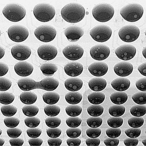
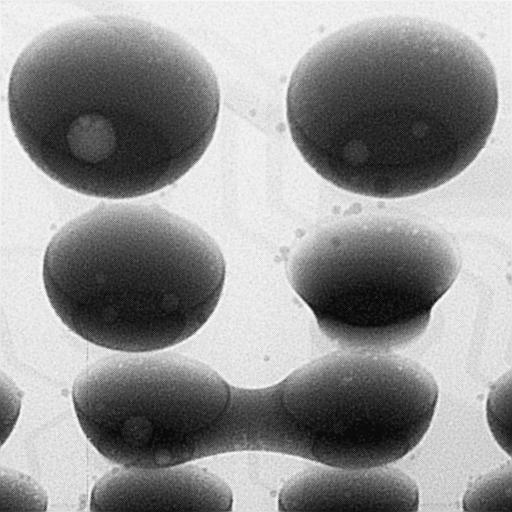
Flat inspection objects (figure 4) such as printed circuit boards with partially hidden solder joints (BGA, FlipChip, THT, QFN, etc.) are also tilted and rotated for angled image capture. Due to the spatial elongation of the X-ray head in the tilted state, however, they cannot be placed closely enough to the radiation source, the X-ray focal spot, to ensure a sufficiently high magnification (figure 5). For this reason, the detector is pivoted instead of the printed circuit board; the microfocus tube delivers a sufficiently large useful-beam cone to make this practicable. The printed circuit board can then be irradiated at an angle for the greatest possible magnification (figure 6). If the pivoting detector is combined with a rotating plate, which can be installed just as quickly as the rotating tilt unit, then angled viewing at high magnification is possible in any direction. Automatic tracking keeps the inspected scene in the image, so that a BGA connection, for example, can be easily observed from all sides.
A real-time image processing system automatically presents the images in optimal quality, without the operator having to intervene when the grayscale value structure of an image changes. Thus, the operator can concentrate fully on evaluation of the X-ray image. The digital image data can be saved in all current image formats for documentation.
Measurement and automation
Because all the manipulator axes are CNC-capable, serial or repeated inspections can be combined in inspection plans. Defective inspection objects are marked automatically. A multitude of analysis tools that can be flexibly adapted to the most various inspection tasks make image evaluation more objective. So the last automation step, evaluation by the operator, can be taken on by the image processing system.
Conclusion
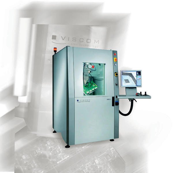
X-ray inspection is frequently employed in areas such as the inspection of safety-relevant components in automotive, aviation and aerospace industries (assembled printed circuit boards, electronic components, etc.). Another main focus is material inspection to find pores and cracks in such applications as welded seams, or contaminants in the pharmaceutical or food industries. Viscom provides the X-ray system X 8011 for many application areas in the quality assurance and nondestructive testing sectors (figure 7). This system can accomplish all conceivable levels of X-ray inspection as described in this article – starting with purely manual visual inspection, through automatic positioning of the inspection object, up to fully automatic image capture and evaluation independent of the operator – and including complete volume reconstruction with computed tomography. The X 8011 also offers the user-friendly XMC operator interface as well as a wide selection of proprietary analysis tools, to ensure the highest level of performance and operator convenience.
SMT, booth 7-211
EPP Europe 457
zusammenfassung
Der Fachbeitrag beschäftigt sich ganz allgemein mit den Möglichkeiten, die die moderne Röntgeninspektion bietet und wo diese erfolgreich eingesetzt werden kann. Vorgestellt wird auch ein Röntgensystem, das in vielen Anwendungsbereichen in der Qualitätssicherung und im nicht zerstörenden Testbereich zum Einsatz kommen kann.
Cet article traite d’une manière générale des possibilités offertes par les techniques modernes d’inspection à rayons X et des domaines dans lesquels celle-ci peut être mise à profit. Il présente également un système à rayons X pouvant être utilisé dans de nombreux secteurs d’application de l’assurance-qualité et dans celui des essais non destructifs.
L’articolo tecnico si occupa in generale delle possibilità offerte dalla moderna ispezione a raggi X e del loro migliore impiego. Viene anche presentato un sistema a raggi X utilizzabile in diversi settori per il controllo della qualità e per controlli non distruttivi.
Share:


