The basic operation of all AOI (Automated Optical Inspection) systems, to date, has been essentially the same in that two-dimensional (2D) imaging, primarily grayscale, is the basis for the system’s analysis and determination of defects. For example, flagging or identifying lifted leads (resulting in opens) is determined by examination of the fillet area of the pad. This is not reliable, however, with smaller, fine pitch devices, where there may be less area available for the machine to inspect and measure. Similarly, lifted components and lifted pads are not easily identified due to the lack of ability to measure the height of a given object or feature. This weakness often results in ‘escapes’, or undetected defects, that impact yields, exacerbate rework, and affect the robustness of the manufacturing process as well as finished product reliability.
Kwangill Koh, Ph.D., Koh Young Technology
Optimizing a manufacturing process for highest yields first requires that all soldering defects must be found by the AOI machine. For AOI, the number of defects found is not the problem; the number not found is. Defects found can then be addressed and solved at the appropriate step in the process. The defects that get by the AOI machine are the source of ongoing process headaches and compromised product reliability. Because the detection of defects is in many cases doubtful, the result is many false calls, because the system cannot “judge” if it is clearly a defect or not. Those false calls require skilled operator intervention, adding to delays, higher costs, and impacting long-term product reliability.
2D inspection is like viewing a landscape from an altitude using only one eye. There is no depth perception. Newly-developed 3D AOI technology allows Z-axis measurement of components, leads, and other assembled PCB topography features, clearly identifying non-conforming items, and eliminating this basic weakness of 2D imaging. 3D measurement can immediately show if one lead, or one side of a component is higher than the others, i.e., not planar to the surface of the board. This is especially effective when detecting lifted leads. 3D AOI also allows far more accurate shape measurement of fillets, which may be critical in many applications. As a result, many types of defects that have been problematical for 2D AOI are now readily flagged using 3D AOI. These include missing, flipped, skewed, lifted, or tombstoned components, overhang, bridging and shorts, opens, solder fillet, coplanarity, component dimensioning, markings, and others in addition to lifted objects.
Differences between 2D and 3D AOI
Real 3D measurement of solder joints was not possible until now. Problems associated with the implementation of 3D measurement had to be overcome. Shadowing problems, measuring range, and erroneous data from warped PCBs had to be accommodated or solved. Additionally, any light measuring system is confronted with specular, reference plane shadow, and directional problems that must also be solved before a useful and practical operating system can be put into production.
A technology has been developed that constitutes a radical departure from existing AOI vision technology in that it senses and measures the vertical or Z-axis height of features being inspected as in addition to the typical X-Y 2D image plane, and combines both, as can be seen in Figure 1. This added Z-dimension measurement solves many of the vulnerabilities of 2D AOI and makes it possible, finally, to detect all soldering defects on an assembly to prevent 100% of escapes. 3D AOI technology is basic in concept. While grayscale 2D imaging is used, the AOI imaging head also employs a series of eight (8) illuminators mounted in a circular configuration to pick up visual data from all sides and the top of the device or feature. It also contains multiple circular rows of LEDs positioned at different heights and angles to the part, each ring firing in succession in different colors, or wavelengths. The camera senses the varying wavelengths and angle of projection of each wavelength onto the part and thus can construct accurate 3D images and measure the height of the component or feature. This configuration allows for completely shadow-free imaging as well as precise position, shape, and height measurement of the feature under inspection.
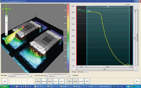
With 2D inspection, the height of objects cannot be determined without some foreknowledge on the part of the person making the observation, as in an aerial photo of, for example, a neighborhood. But since the peaked roofs of houses in an aerial photo all look the same from the sky, there is no way to tell, without a side view or element of depth perception, whether or not all the buildings are single story or multi-stories in height. A human observer examining such a photo may be able to correctly make such distinctions based on many subtleties of personal judgment, whereas a machine is far less capable. The same is true for lifted leads, and lifted components. 2D AOI cannot determine whether or not these components are at the proper height for an object connected to the PCB. 3D sensing can immediately show if one lead, or one side of a component is higher than the others, i.e., not planar to the surface of the board. This is especially effective when detecting lifted leads. 2D AOI uses fillet shape to determine the status of leads, and with very small fillets, it is inadequate. 3D Lifted Components
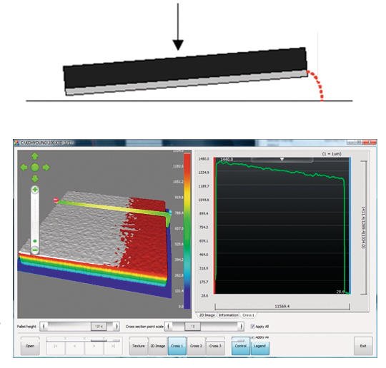
AOI also allows far more accurate shape measurement of fillets, which may be critical in many cases. The problem presented by a lifted component is an excellent example of how 3D AOI can flag a defect that would otherwise not be detected using 2D AOI. As Figure 2 illustrates, a lifted component may not be detectable using 2D AOI because it cannot measure height variations across the surface of a component. Yet, a lifted component is a serious defect requiring rework, as well as attention to its cause in the manufacturing process. 3D AOI not only shows the obvious differences in height across the component – thus being able to flag it as a defect, not a false call, and certainly not an escape – but also accurately measures the telltale variation in height (as per Figure 2.).
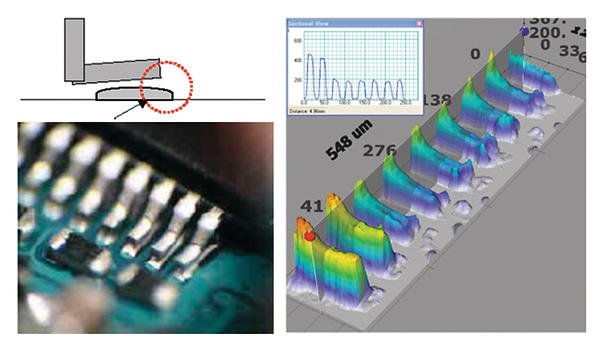
Lifted Leads
Similarly, the problem of lifted leads constitutes a serious defect that 2D AOI has trouble flagging. 2D AOI makes a judgment about whether a lead is lifted by examining the fillet area, for lack of other criteria. In Figure 3, we see an example of the area under examination. However, if the fillet area is small, it’s very difficult to inspect accurately using 2D image. The photo image shows an area of leads where some are slightly lifted off the pads, resulting in opens, but would be difficult to detect. In this case, 3D profilometry shows without question the fact that the leads are lifted and constitute a defect. This is because the Z-axis measurement capability has made much more information available to the AOI machine, enabling it to make an accurate judgment call.
3D AOI Compares Images with CAD Data, IPC 610
The real value of 3D AOI is magnified by a key aspect of how it functions – template comparison based on the IPC 610 Acceptability Standard. This factor cannot be over-emphasized; its value is such that it removes any question of the inspected object’s acceptability or non-acceptability, and does not require a decision-making intervention on the part of the operator. Thus, the equipment can be run by a trained technician who does not need to be well-schooled to make go/no go defect decisions or interventions in the inspection process. Machine calls are based on a globally-accepted standard. Programming is therefore much simpler and based on CAD data. Coplanarity issues, component polarity, lifted leads, tombstoning, and other defects are quickly and unmistakably detected and confirmed based on these two sources of authoritative reference.
Conclusion
Manufacturing engineers using AOI are not concerned about the defects that their machines find, but rather the escapes that the machine does not catch. The consequences of then trying to push their machines beyond their limitations – which are imposed by the inadequacies of 2D imaging data – are false calls. The solution is improved data – 3D imaging and measurement – by adding another dimension (Z-axis) to the 2D information already used by the AOI system. 3D AOI effectively negates all of the shortcomings of traditional 2D AOI and eliminates virtually all possibility of escapes while also preventing false calls due to shadowing and specular problems that have long been the primary vulnerabilities of 2D AOI.
SMT/Hybrid/Packaging Booth 7-415
Zusammenfassung
Die Grundaufgabe aller AOI-Systeme besteht darin, mithilfe einer 2D-Abbildung, meist in Graustufen, Bestückungs- und Lötfehler zu finden und zu analysieren. So werden beispielsweise fehlerhafte Lötstellen über die Prüfung des Lotbilds im Übergangsbereichs des Kontakts ermittelt. Dieses Verfahren ist nicht wirklich zuverlässig, da dem System mit zunehmend kleineren Bauteilen immer weniger Fläche für die Prüfung zur Verfü-gung steht. Gleichermaßen lassen sich angehobene Bauteile bzw. Kontakte aufgrund der fehlenden Fähigkeit, die Höhe eines vorgegebenen Objekts zu messen, nur schwer indentifizieren. Dies führt oft zu Kosten, Schwächen im Ferti-gungsprozess und geringer Produktqualität.
La mission de base de tous les systèmes AOI, la saisie de données, est en gros toujours la même dans la mesure où une représentation en 2D sert de base à l’analyse et à la détection de défauts. Ainsi, par exemple, les points de brasage défectueux sont détectés par le contrôle des zones de transition du contact. Cette méthode n’est pas vraiment fiable dans la mesure où la miniaturisation des composants offre une surface toujours plus petite au contrôle. De la même manière, les composants ou contacts en relief sont très difficiles à identifier en raison de l’inaptitude des systèmes à mesurer la hauteur d’un objet prédéfini. Cela abouti entraînant des dépenses ainsi que des défaillances dans le processus de production et dans la qualité des produits.
Share:


