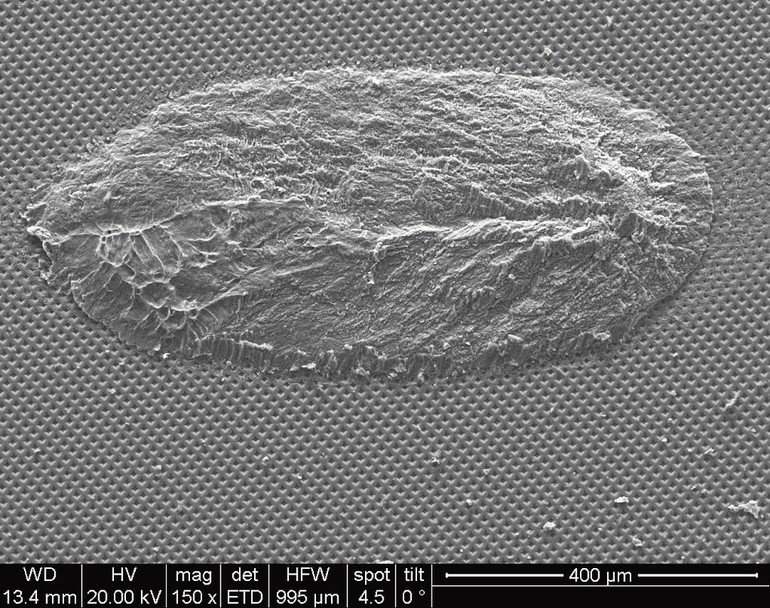
The most widely used such test is the Active-Power-Cycling-Test with active load cycles. The component is energized under quasi-real conditions until a defined temperature rise is observed; these load cycles are then repeated until the component fails. The main variables here are the temperature swing that occurs, the initial temperature and the cycle time, which is usually a few seconds. Due to the significantly different CTE (coefficients of thermal expansion) of bond wire (aluminum) and semiconductor chip (silicon), the heating generates a mechanical load that eventually causes cracks at the ends of the wire bond after many thousands of cycles. Over time, these cracks then travel through the entire bond until the connection lifts off and the component fails.
Disadvantages of active cycle test
It is obvious that such a cycle test is time-consuming: even with a relatively short cycle time of 5 seconds and a service life of only 100,000 cycles, the measurement takes almost 6 days. For a component (or test scenario) with ten times the service life, the measuring time would then be almost 2 months. It is therefore becoming increasingly difficult to develop components with ever longer service lives, because it can take several months just to decide between several process variants. Consequently, it is no solution either to further accelerate the tests by, for example, increasing the temperature stroke and thus the thermo-mechanical load. Although this usually leads to an earlier failure, the mechanism of fatigue can be different from that at a lower temperature swing – and the significance of the test is therefore limited.
This is not even the only weakness of the PC test. As a quality control during production, or to ascertain that process changes, different component suppliers, etc. do not have a harmful effect, the long test duration bears the risk that, in the worst case, several weeks worth of production might have to be discarded or devalued.
The magic solution, to the latter problem in particular, would be a rapid test that, like a kind of time machine, accelerates the test and allows at least semi-quantitative results or comparisons between different component batches.
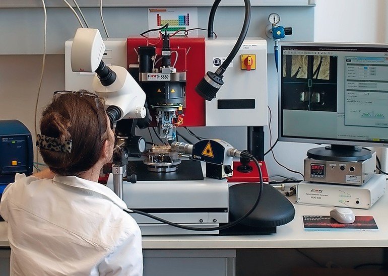
Dr. Khatibi‘s research group at the Vienna University of Technology has developed such a rapid test, which has since been implemented on an automated Bond tester, the F&S Bondtec 5600C, in the framework of a Christian Doppler Laboratory with F&S Bondtec, Braunau/Austria, and is now available as standard commercial equipment.
Straightforward rapid testing
The process is based on a simple idea: during a temperature change, the aluminum bonding wire expands almost nine times as much as the silicon base of the chip – the wire tugs at the connection interface, so to speak. This tensile stress occurs mainly along the wire axis, because a heavy-wire bond is considerably longer than wide. Precisely this mechanical tension can be reproduced by gripping the bond wire at the bond foot with a clamp and pulling it back and forth along the wire direction. The movement amplitude must be as large as the expansion at the corresponding temperature stroke.
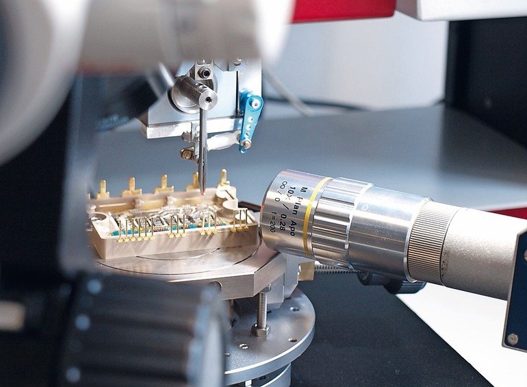
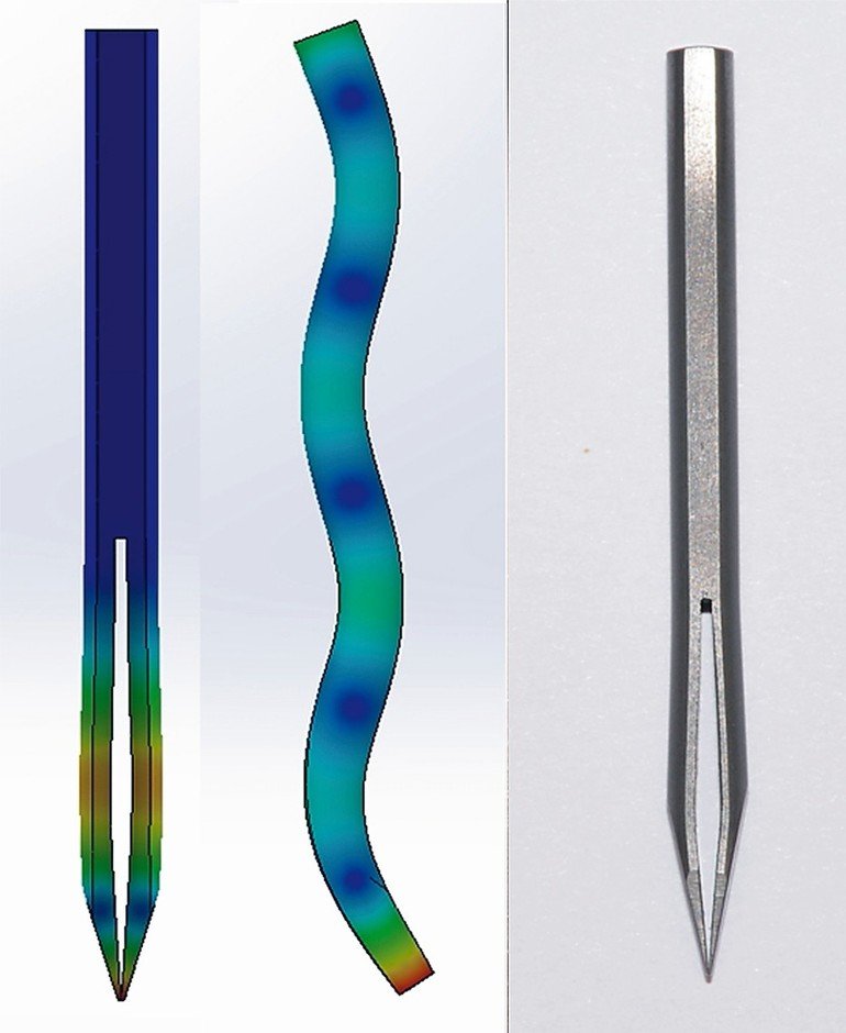
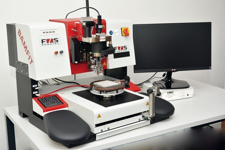
This principle was implemented in the BAMFIT Bond tester (Bondtec Accelerated Mechanical Fatigue Interconnect Test), based on a heavy wire bonder. The crucial new technical development, now patented, is a forceps clamp which is mounted in place of the bond tool and can grip and clamp the bond foot. In addition, it functions exactly like a bond wedge, i.e. it is mechanically excited by an ultrasonic transducer at 60 kHz and vibrates in resonance. Made of special steel, it is pre-stressed inwards so that the tip closes with a constant and defined clamping force. It can be opened by an external mechanism so that it continues to work in resonance when closed. With this clamping device, the opening width can be freely controlled and adapted to the space required, so that closely adjacent wires can also be gripped. Each resonance tweezer clamp is specially dimensioned, and the clamping strength and tip size are adapted to the wire diameter and material to be tested.
The entire process was realized on the platform of the Bondtec 5600 automatic Bond tester. This device features interchangeable bond or test heads and allows programmable, automatic operation at any number of test positions, even with automatic image recognition for accurate and reproducible positioning. Other functions of the automatic tester, such as automatic height measurement with touchdown, have also been implemented.
The BAMFIT test head is simply exchanged for another bond or test head on the machine base, so that standard pull or shear tests can be carried out interchangeably. If the machine already has an ultrasonic generator, this is also used for the tests. The machine software is identical to that used for bonding or testing. The training effort for the new test procedure is therefore comfortably low.
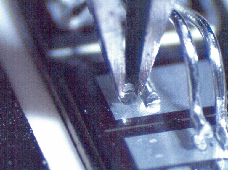
A test run is straightforward: First, both the position and direction of the wedge bond contact are precisely located, and the clamp is then opened so that the clamp tips move past the wire as they are being lowered. Touching the bond surface is detected by the touchdown sensor; the clamping tweezers are then raised to the programmed clamping height and closed. In this state, at a defined distance from the bond surface, the bond wire is mechanically connected to the 60 kHz transducer from both sides with a constant clamping force via the clamping jaws.
These clamping jaws are slightly longer than the wedge bond foot so that they project beyond it and achieve the largest possible clamping surface. During the entire duration of the ultrasonic signal, the bond force device applies a small constant tensile preload in the Z direction to prevent the connection from frictional re-bonding. This upward pull is so small that no additional damage is caused. The height sensor now allows to determine the exact time of failure when the wire lifts off.
Efficient process optimization
The ultrasonic power at the transducer can be adjusted and is directly proportional to the oscillation at the tip of the clamp jaws. These cyclic deflections are well below 1 μm and are therefore much lower than for the actual bonding itself. Depending on the amplitude applied, the number of cycles until complete lift-off is in the range of about 104 to 108 and above. At an excitation frequency of 60 kHz, 10,000 cycles correspond to a measurement time of approx. 160 ms, which can still be clearly resolved at a measurement interval of approx. 15 ms. In a typical service life range of 10 to 100 times more cycles, a very acceptable measurement time of approx. 1.5 to 15 s is achieved. Thus, a rough lifetime prognosis is achieved simply by measuring the time from switching on the ultrasonic oscillation until the wire detachment.
In this way, an entire layout can be programmed and tested automatically in a very short time. Start (source), middle (stitch) or end (destination) bonds can be gripped and tested in the same way, as long as they are accessible from above, similar to the bonding itself. For the precise positioning of already existing bonds, the program and the image recognition unit (PRU) of the Bond tester can be used advantageously for previously bonded wires.
As a result, the number of load cycles until final lift-off is determined as a function of freely programmable oscillation amplitudes, which can be converted into shear stress values at the joint. There is a correlation between pure mechanical stress amplitudes and the reference junction temperature differences (∆ Tj) for PC tests. Finite element analyses can be used to convert between the thermally and mechanically induced stresses in the contact interface with great accuracy. The mechanically determined lifetime curves show remarkable good agreement with results from PC tests in the ∆ Tj range 50 to 160 K for the same failure pattern, a bond wire lift-off.
The mentioned tester is already in series production with first manufacturers of power modules. It is expected to make a valuable contribution to efficient quality assurance and simpler process optimization for thick wire bonds. Further developments for the extension of the technology to copper heavy wire bonds as well as ball bonds with copper wire are already underway and are also showing very positive results.
Zusammenfassung
Bond-Drahtverbindungen müssen über mehrere Dekaden und unter hohen thermomechanischen Belastungen zuverlässig halten. Dafür sorgt ein Bondtester mit einem extrem schnellen automatischen Qualitätstest zur Lebensdauerbestimmung der Bond-Drahtverbindungen.
Résumé
Les connexions des fils de liaison doivent être fiables pendant plusieurs années et résister à des charges thermomécaniques fortes. Ceci est réalisé par un testeur de liaison dans lequel est incorporé un test de qualité automatique et rapide ; ceci afin de déterminer la durée de vie des connexions des fils de liaison.
Резюме
Контактные соединения с использованием гибких металлических проводников должны служить десятилетия в условиях серьезных термомеханических нагрузок. Качественное соединение можно обеспечить только при использовании высокоскоростного тестера, позволяющего в автоматическом режиме осуществлять контроль сварок.


