The electric mobility sector needs more sophisticated quality inspections for electronic assemblies as a classification of the inspection results in good and bad parts is no longer adequate. Viscom is responding by continuing to enhance its inspection technologies, delivering more precise measured values that increase the effectiveness of efforts to optimize even further production processes.
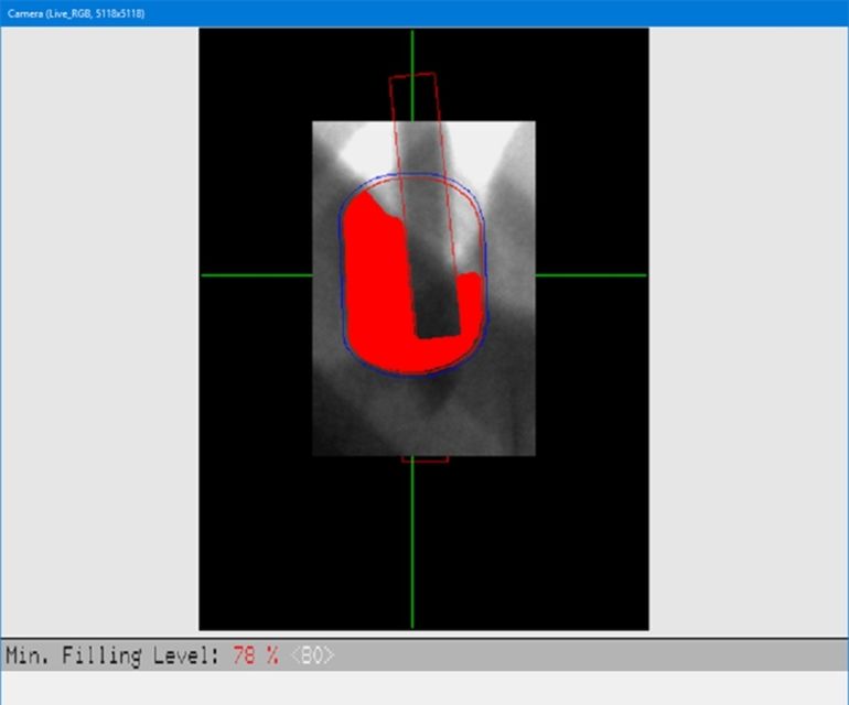
The trend toward electric mobility is resulting in increased requirements for the durability and safety of electronic assemblies – and the stability of solder joints is a particular focus. Quality inspections according to DIN 1319 allow an inspection object to be classified as good/bad. An inspection of this type determines whether the characteristic values fall within defined thresholds, or tolerances. However, these inspections are insufficient when it comes to evaluating gas inclusions (voids), the filling level of THT solder joints, the heights, positions and the alignment of components. Accurate measured values are the only valid indicator of how well the IPC guidelines or a company’s own requirements are being maintained. The same is true when it comes to the actual distance between anodes and cathodes in lithium-ion batteries. Precise measurements are also needed here.
Exact measured values make process trends and variations visible. This allows for a more effective assessment of where the production process needs to be readjusted and improved. Changes can be implemented before defects occur. The goal is for AOI and X-ray inspections to continually relay information back to the paste printer and placement machine. The production systems regulate themselves, and processes are optimized on an ongoing basis. But the prerequisites for this are very demanding: a higher degree of measuring resolution and accuracy, a higher data rate, and the rapid measurement and transfer of data to inline systems.
Measuring data for void inspection of solder joints
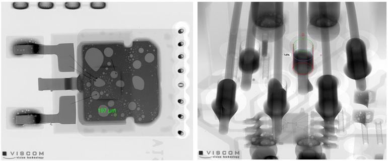
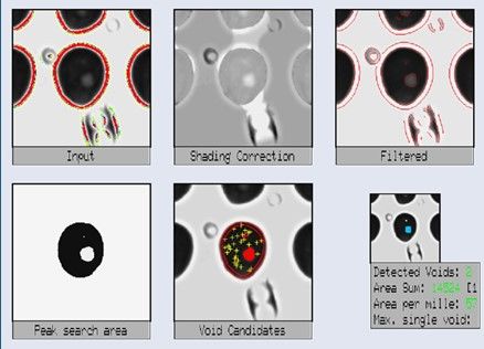
Large cavities in solder joints, so-called voids, can significantly shorten the service life of products. Voids reduce the thermal and mechanical strength of solder joints (temperature cycles, shearing strength). In addition to power components and LEDs, this also affects BGAs, QFNs, transistors and THT components in general. Voids are caused by a number of interacting factors such as contamination, the selected solder paste, melting behavior, the temperature profile in soldering ovens, the selected soldering flux, etc.
AOI does not detect voids. Electrical function inspections can also yield error-free test results, even though the solder joint is not thermally stable due to voids, which puts the safety of the product at risk. An X-ray inspection is the only method that shows the position and distribution of gas inclusions, with 2D, 2.5D and 3D offering various inspection options.
- 2D X-ray inspection: With this method, the X-ray beam strikes perpendicular to the solder joint being evaluated and provides a direct measurement of the size of voids. The advantages of this method are that the inspection is completed very quickly and components are exposed to low levels of radiation. But its effectiveness is limited when it comes to shadowing by absorbent material on the underside of the PCB in particular.
- 2.5D X-ray inspection: In this case, the images of the solder joint to be inspected are taken at an oblique angle to the PCB. The advantages are that the inspection position is selected so there is no shadowing. The inspection is completed very quickly and components are only exposed to low levels of radiation.
- 3D X-ray inspection: This method takes 2.5D images of a single plane at different angles (tomosynthesis / planar computed tomography). The higher the number of captured images, the better the quality of the 3D slice images. The advantages are that this method produces images of a very high resolution and the inspection positions have no shadowing. However, the inspection time increases as the number of captured images increases, which means the components are also exposed to higher levels of radiation.
- Best mix of AXI 2/2.5/3D: Combining the technologies allows for targeted optimization of the performance and coverage of the X-ray inspection.
Inspection systems like the X7056-II 3D AOXI offer combined automated optical and X-ray inspection. The combined solution consisting of an X-ray (AXI) and optical inspection (AOI) in one single system optimizes the inspection’s coverage and speed while keeping the radiation affecting the component to low levels – making it the most effective inspection solution available.
Faster measuring for inline inspection
A number of conditions need to be met so the results of the X-ray inspection meet quality requirements and can be used to improve processes. The measured values have to be reproducible and accurate when repeated (machine transferability), their measuring resolution must be of a sufficiently high quality and they have to be verifiable (calibration material). The suitability of the measuring system is verified by means of a measuring system analysis (MSA) performed on a certified calibration material.
Viscom has achieved significant advances in terms of measuring accuracy and speed. The integrated flat panel detectors (FPD) deliver measured values that are 3.2 times more stable than the corresponding image intensifiers previously used. Moreover, X-ray inspection was too slow for inline process monitoring prior to this. The current evaluation computers use the graphics processor (GPU) as well as the main processor (CPU) to execute calculations in parallel, thus considerably accelerating the process. Such progress makes fully automated inline X-ray systems with shorter exposure times and faster analyses even for high-quality 3D inspections possible.
In addition, a higher sensor resolution enables finer sampling rates, resulting in a very high resolution of up to 6 µm in 3D inspection. Improved algorithms make it possible to analyze the image data in the pixel range as well as in the sub-pixel range. The algorithms ensure that any interfering signals are suppressed and the measuring signals can be evaluated without interference. In addition, the effort involved in programming X-ray inspections is significantly reduced once again thanks to the improved algorithms. Configuring threshold and tolerance values is much easier as a result.
Plus, regular grayscale value calibrations and corrections ensure better reproducibility. The FPD can also be moved by a wear-free X/Y-axis system, enabling three-dimensional evaluations at different stages of quality and throughput.
Improved measuring data from the 3D AOI
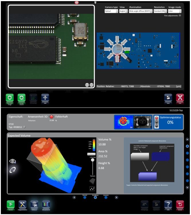
2D and 3D methods also offer a range of measuring tasks for automated optical inspection. Besides evaluating solder joints, exact detection of component orientation is also an increasingly important application. In the ever-smaller LEDs that are increasingly being installed in vehicle lamps and headlights, even minimal tilting is a defect.
- 2D AOI methods are suitable for measuring offset (acc. to IPC class 3) and twisting.
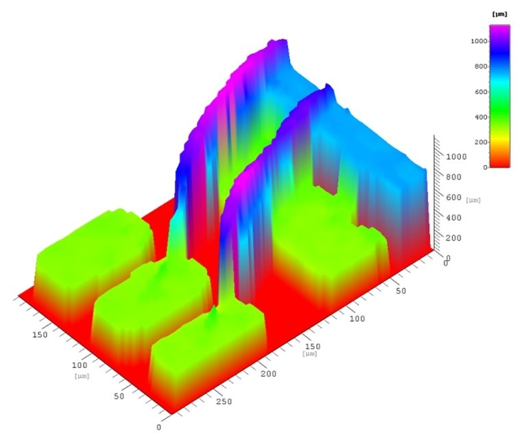
- 3D AOI methods are suitable for simplifying the identification of component bodies (e.g., dark components) and measuring offset (acc. to IPC class 3), twisting, component height, component tilt, coplanarity, the height of individual pins, wobble circle, solder volume and solder profile. 3D methods attain an x/y-resolution of 10 µm and a z-resolution of 1 µm. With these methods as well, improved algorithms make it possible to analyze the image data in the sub-pixel range.
- 2D/3D AOI methods: Thanks to a combination of features, measuring and inspection results can be further enhanced.
The AOI systems achieve a similarly high level of precision as that offered by special measuring microscopes, but they do so at a speed required for inline systems. The migration of 3D technology to the wire bond inspection also enables more accurate measurement results thanks to the additional height information.
Company contact
Viscom AG
Carl-Buderus-Str. 9–15
D-30455 Hannover Germany
Tel.: +49 511 94996–0
E-Mail: info@viscom.de
Website: www.viscom.com


