


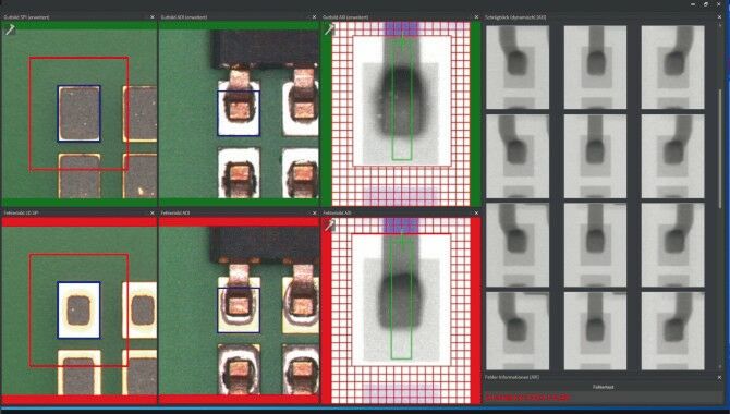
An AXI system is absolutely comparable to an AOI system – only the images are not as beautifully colourful,” jokes Andreas Türk, product manager AXI at Jena-based testing and inspections solutions provider Göpel Electronic. The company’s most recent AXI systems offer a wide array of features including fast-scanning image acquisition; inspection programme creation; industry 4.0 integration; and, thanks to the digital predictive maintenance concept, self-monitoring. In addition, the systems are all connected within one network. If an anomaly is found, data from the SPI, AOI and AXI systems is displayed together on the verification station. This helps operators track down the source of the fault.
Image acquisition tech
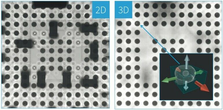
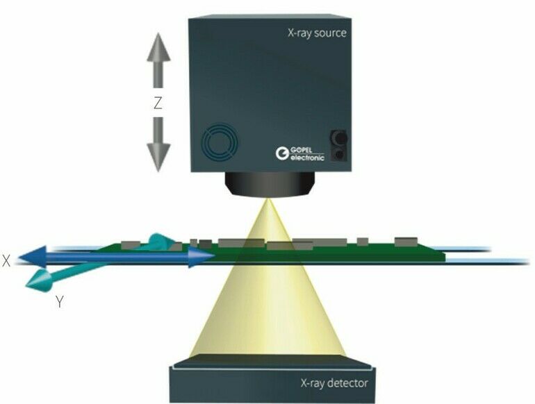
The newest AXI systems are able not only to scan assemblies vertically (so-called 2D) or at an oblique angle (so-called 2.5D) in order to inspect solder joints, but also using a technique called 3D x-ray inspection. This technology allows for the inspection of solder joints in several layers and, as such, offers the highest degree of defect detection and coverage. In part, it is the combination of all three image acquisition technologies that provides the best inspection result. Since 3D technology generates a synthetic 3D image using several obliquely-captured images (in a process known as image reconstruction), the image acquisition time is longer than when using conventional 2D or 2.5D technologies. 3D systems with flat-panel detectors struggle here because the time for stop-and-go movement of the axes is significantly longer than the actual time required for image acquisition. „As a rule of thumb, when using eight oblique images for a 3D image field, you can expect an image acquisition time of about 3–5 seconds,“ explains Türk. Depending on the image field size and the number of 3D image fields required, this can add up, and the acquisition time for a high-runner product is too long. Göpel has come up with a solution for this.
Cycle time reduction
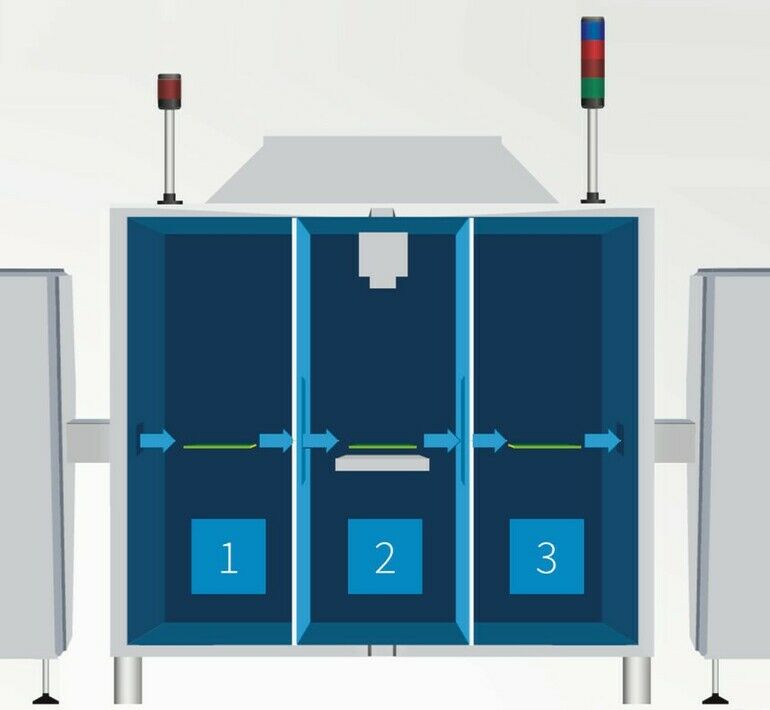
The company‘s AXI system X Line 3D relies on line detectors to keep image acquisition time low. Several detectors take 2D, 2.5D and 3D X-ray images in parallel, and in motion. This concept makes it possible to inspect larger areas of the PCB or complete multiple panels in 3D. In addition to the image acquisition time, the time for PCB handling, image processing and optional MES export are included in the total cycle time. For this reason, X Line 3D systems have a three-chamber principle. There are three PCBs in the system at one time in inline mode. Once image acquisition of the board has been completed, it is immediately moved out of the beam path into another chamber. This is where post-processing takes place. This reduces both total cycle time and radiation exposure for the components.
Intelligent PCB handling
Over the years, the systems have also become smarter in terms of PCB handling. The PCBs that are inspected by AXI systems vary in size, weight and friction coefficient, among other things. In the past, these differences were not taken into account and PCBs were always transported at the same belt speed. This can take up valuable cycle time. For this reason, the X Line 3D system belt transportation system independently learns the optimal belt speed by means of intelliFLOW. After an automated teach-in process, the machine stores the optimal transport parameters specific to the inspection programme.
Usage-based maintenance
System downtime for maintenance work is often problematic. At Göpel, systems use a service & maintenance app which creates usage-based maintenance plans in advance and monitors the machine. Self-diagnosis using predictive and preventive maintenance management ensures stable machine conditions and repeatable, consistent performance. Every key component of the machine is monitored and a detailed maintenance summary is generated. A preventive maintenance plan reduces machine downtime and therefore costs. On a practical level, work no longer has to be carried out according to scheduled maintenance cycles. Instead, usage-related values (such as kilometres travelled by the axes; pneumatic strokes, and X-ray source radiation hours) are monitored. These values are given a warning and service threshold. If the warning threshold is exceeded, preventive maintenance can be initiated. The app enables operators to simultaneously monitor several machines. This makes maintenance easier to plan and reduces downtime.
Human-machine interaction
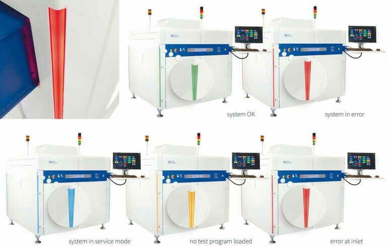
Human operators will certainly continue to be required in 2022, as the enhanced human-machine concept demonstrates. Consisting of light bars integrated into the system‘s external design in the corners of the exterior cladding, these enable operators to check the statuses of various systems easily and quickly and even from a distance. This helps operators to react quickly and avoid a line stoppage. In basic operating modes, static colours are used to indicate if machine is checking, waiting, is in service mode or has a fault. In the event of an error, a distinction is also made between the left and right sides of the machine. If there is a problem with the PCB infeed on the lefthand side, it lights up red. A lack of material in the infeed or a PCB jam in the outfeed is also signalled using coloured lights. In addition to static colours, certain functions are also represented by animations. The x-ray source warm-up is indicated by a progress bar, for example. The results of the last ten inspected assemblies can also, for instance, be displayed in statistical form.
Lower radiation exposure
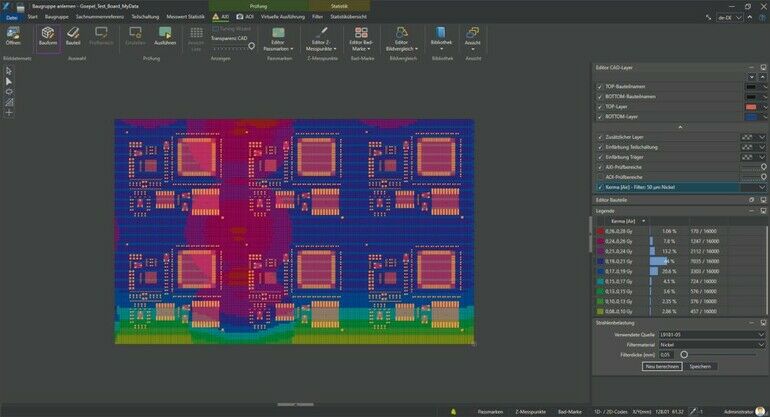
Reducing the time that components are exposed to radiation is becoming increasingly important. The X Line 3D tries to keep radiation exposure low in several ways. Firstly, low-energy radiation components that do not directly contribute to imaging are reduced via filters in front of the x-ray source. Secondly, the assembly is transported out of the beam path onto another belt module directly after the image has been acquired in order to avoid unnecessary radiation. Thirdly, the fact that the image acquisition process has very short exposure time minimises the dwell time of the test specimen in the beam path. This further reduces the components‘ radiation dose. The offline programming software Pilot AXI has an integrated calculation tool for calculating the radiation dose.
Common defect display
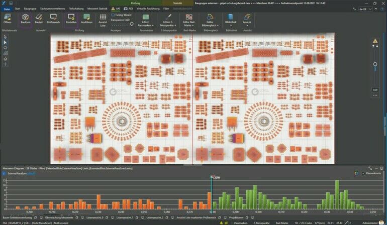
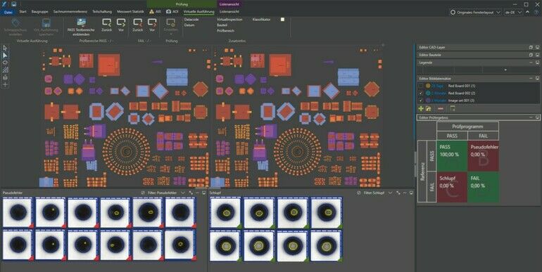
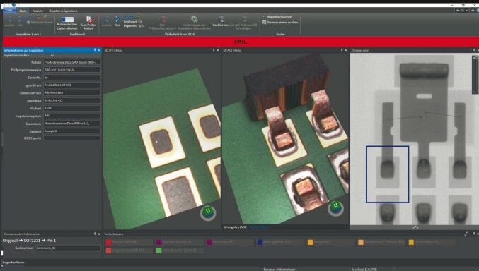
The test results and measured values generated by the AXI are stored in a central database. These can be used by humans to classify the defect as well as to help optimise the entire process. Göpel‘s Pilot Connect software is at the heart of the central data storage. Here, the date from the SPI, AOI and AXI are merged together and can be jointly displayed on the verification station Pilot Verify. Devices from other manufacturers can also be connected. The evaluation of automatically detected anomalies is taken into
account to avoid common error displays. AXI systems are connected to MES by our own software team during delivery.
Conclusion
Since the first manual and automatic X-ray systems found their way into electronics manufacturing, the industry has experienced enormous technological leaps forward. While system performance continues to improve, test specimens are becoming ever more miniaturised and thus more difficult to inspect using conventional methods. Additionally, high throughputs and more closely-timed production processes call for a tighter framework. X-ray systems such as the X Line 3D have been specifically adapted to these conditions and will play a major role in component inspection in the future.
Electronica, Booth A3.351


