For tests of wireless appliances, special fixtures are needed. These products radiate electromagnetic energy that can interfere with other devices under test (DUT). Such a DUT also receives electromagnetic signals from a test source, and other sources might interfere. Radio frequency (RF) interference is the primary reason that the adaptation requires isolation, attained by carefully performed design.
William G. Jones, Agilent Technologies
The number one user’s goal for high-volume manufacturing test adaptation is usually low cost, normally stated in many terms such as low cost of purchase, highly reliable, low cost of maintenance, safe for operators, easy to use, etc. Using a cost-model, it can be shown that an adaptation which costs more and meets all of the other requirements can in fact meet this goal better than a cheaper version, not adequately meeting the demands. Achieving and maintaining the needed RF-isolation from inside the fixture to the outside complicates nearly all aspects of design and use. How can we meet all these concerns? For mobile-telephone application, let’s divide the issues into four environments: RF, audio, physical and operational.
Isolation of inside and outside environments
We need to isolate the phone from the ambient RF environment. For this, we need a metal box that is sealed to prevent leakage, yet be able to open and close easily to permit loading/unloading. The box can also become an echo chamber for the RF inside. Most phones make their main RF-connection via coax cable (galvanic contact). Over-the-air testing is also performed part of the time to insure proper antenna connection has been made. Some phones do not have a galvanic connection and must utilize the over-the-air link. In this case, the RF environment is even more critical.
The DUT isolation from the ambient environment follows a simple concept: keep the RF in the box from escaping and prevent RF outside from getting in. The hard part is achieving this and knowing that this has been attained. Lots of near-field and far-field tests are needed, using vertical and horizontal polarizations and all sides facing the external antenna, and with both the source inside the box and outside. Where the antenna is placed inside the fixture can also make a huge difference. Therefore, the transmitting antenna must be placed in multiple locations inside and tested for leakage to the outside, as well as putting a receiving antenna in multiple locations inside and testing for leakage from the outside – these across all used frequencies. Seals may not be as effective after a few thousand operations as they are when new. So, checks must be repeated after many hundreds or thousands of operations, to determine when to expect the isolation to drop below requirements.
To perform this testing requires an RF-anechoic chamber as well as an open range, antennas, sources and receivers. These measurements are quite time-consuming and costly. The isolation is recommended =60dB, to assure that RF interference is not reducing manufacturing quality or yield. A very common problem is when a DUT fails a production test, and the repair technician cannot repeat the failure. This no-trouble-found (NTF) DUT goes back to the test system where it may or may not pass when checked again.
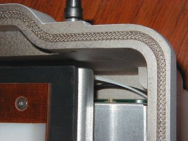
Examining the parts of the fixture that play a key role in achieving the needed isolation, there are two sites where RF-leakage can occur. Since the mechanism must be opened and closed, there will be operational joints. We must pay close attention to the design of each joint as well as the type of gasket material for sealing. A joint must have extremely good alignment and make firm contact with the gasket. The surface of all joining parts must support a good galvanic connection over the life of the fixture, and must not corrode. Special attention must be given to the type of plating used (see figure 1).
Penetration issues and life cycle
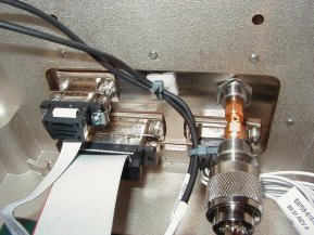
Then we examine where power, compressed air as well as communication and control lines penetrate the fixture wall. For signals, we can use a filter-connector to reduce RF-energy from passing through where it is mounted. Too much filtering and communication and control lines may not work correctly, too little, and RF-leakage may occur. A bit more creativity is needed to address the compressed air lines. We must allow the air to flow and stop RF-energy (see figure 2).
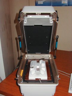
Once we achieve fixture joints and penetrations that prevent RF-energy from leaking, it needs to be maintained. How can this be accomplished? The fixture must be rigid over time so as not to compromise the joints. In a sealed fixture, the RF environment inside might not be as good as we expect. We place a transmitting wireless appliance inside, and the energy will continue to reflect off of the fixture walls. Some of the RF-energy will be absorbed by the appliance and be the cause of malfunctioning. The ideal place to test a wireless appliance would be in free space. Since this is not at all practical, we must approximate free space inside the fixture. Placing an RF-absorber material inside the shielded box will reduce the energy that is reflected. Each time RF-energy passes through the material, part of it is absorbed. After a few reflections, the RF-energy will have been sufficiently attenuated so as not to disturb the operation of the wireless appliance (see figure 3).
A good direct RF-connection to the DUT is critical for making accurate power measurements. These connectors can easily be damaged in a test fixture. The design of the connector engagement has to be done with care. Self-aligning and floating connectors are recommended, thereby reducing wear and improving contact integrity. Using a spring-loaded stop-lock can prevent overinsertion. Using a fixed connector may require replacement every 1,000 cycles, and a floating version may last 10,000 to 20,000 cycles.
How do we prove that the RF-environment is good after all of the controlled testing? Run repeatability tests, run the same procedures many times on the same DUT without opening the fixture to minimize the variables, and calculate the Cpk values for each test. Once that is good, then add variables such as inserting and removing the same DUT for multiple tests. Next insert and remove different DUTs multiple times, etc. At each step, in other words for each variable added, correct what needs to be changed to achieve a good Cpk. Cpk is a measure of test repeatability and the probability of passing. A test with good repeatability is not enough. If the mean of the test data is near one of the limits, the probability of tests failing simply due to the probability of tests that result in a value that crosses the test limit can be significant. The goal here is a small sigma or standard deviation, and having the mean of the test data well centered between the limits. The computation of Cpk takes all of this into consideration.
Combat of measurement errors
Now we turn our attention to the area of susceptibility to measurement errors. If audio testing is used to test the transducers of the DUT with more than just a Go/No-Go test, then having a quality audio environment is critical. The DUT must be isolated from the manufacturing environment, and have a proper audio transfer between the transducers and fixture. These tests assume that the DUT can redirect audio signals from its transducers to the system plug of the DUT. If a vocoder is part of the audio path, it is not possible to determine the quality of the DUT transducers. As with the RF-isolation problem, the audio integrity of the fixture is important in achieving reliable tests. Not properly addressing this issue in the fixture design can result in „false“ failures. To prevent a fixture from changing the transfer function of the audio between the DUT and the fixture transducers, the DUT must be isolated from the fixture. This prevents both the dampening and resonances resulting from hard physical contact. The fixture design must also prevent air reflections within the fixture cavity that result in incorrect measurements. How much isolation is needed? In the frequency range of 500Hz to 2kHz, it needs to be about 20dB. The isolation of the fixture from the ambient environment needs to address the lower frequencies resulting from shop-floor vibrations, and should cover 200Hz to 1kHz with an attenuation of 15dB. The primary source here is the surface on which the fixture sits. To get the correct transfer function between transducers requires that the fixture audio paths emulate the real-world audio paths. This is the path from mouth to microphone and the path from speaker to the eardrum must be correctly emulated.
Another item that can be easily overlooked or be a hard-to-identify source of error is the effect of RF on electronics inside a fixture. Affected audio electronics can result in a source of noise and offset in the signal to or from the transducers. This is most noticeable in the microphone circuitry because of the low voltages involved. In the physical environment, it is common to find some of the most important details of this area overlooked. Some of these details are: holding the DUT correctly, detecting that the DUT is properly loaded, and providing good RF and electrical connections. For some applications, detecting that the DUT is in the nest is important. The simplest way is to use a small switch that is actuated when a DUT is in the nest. Other ways are multiple mechanical switches, magnetic switches, optical beams being either broken or reflected or combined. For automated fixtures, this detection is necessary to allow the phone to be clamped into the nest before the connectors can be inserted. If audio isolation is needed, the clamping action may need to be released after the connections are made, to pre-vent an adverse effect on the audio transfer-function.
Always important: good connections
Connections to the DUT are critical to the long-term reliability. When DUTs are plugged and unplugged 300-times a day, the connectors will wear out quickly. Wear-out connectors must be of high quality and easily changeable. To enhance connection quality and improve the life of such parts, we use floating and self-aligning versions. The absolute position of a floating connection is not fixed relative to the DUT. As it mates with the DUT connector, it should be guided into the proper orientation by mechanical design of the connector mounting and therefore aligned. If this is not done, then each time the connectors are engaged there will be excessive wear, and the possibility of breakage and of intermittent or bad connections increases. These conditions lead to an increase in „false“ test failures, and fixture maintenance leading to minimized throughput. When automatic keypad actuation and/or visual inspection are required, the equipment needed to perform these must not interfere with the RF or audio environment. The designer has to assure that it is implemented correctly. For example, a matrix of fixed actuators may interfere, whereas a moving actuator could be shifted out of the way for tests. For vision inspection, achieving proper alignment of the image is done best in the computer, rather than clamping the DUT into the exact pixel reference and rotational position. This can be accomplished by pattern-recognition software, and is faster than pixel comparison.
There are also some operational environment issues that deserve attention: personnel safety, fixture-to-tester interface, reliability and maintenance. It is important that no one is injured by the operation of a fixture. We would not want the fixture to actuate when the operator has his fingers where they could be hurt. This may mean placing two buttons such that it requires both hands to press them simultaneously to actuate the fixture, and they need to be placed on safe locations. Another way is to reduce speed and pressure so as not to cause harm if fingers are caught. Additionally, only actuating the inside mechanisms after the fixture is closed would prevent any injury.
The difference between a good and bad adaptation
Next, the fixture-to-tester interface must not be overlooked. The design should permit quick, easy and error-resistant fixture changes. This will minimize downtime due to fixture failures or product changeovers. If the fixture is designed for interchangeable DUT nests, can the change of the nest be done easily and quickly? If the fixture has to be changed, is it easy to disconnect and reconnect all of the cables? If not, should the fixture be divided into two parts? One element would be a docking station, always connected to the tester, and the other part has the DUT nest, which can be easily removed for quick changeovers and maintenance. A suitable solution must be determined by analyzing the interface between tester and fixture, and the cost of customization for the DUT nest.
Then reliability and maintenance must be addressed. In addition to using self-aligning and floating connectors, easy maintenance is crucial to reliability and up-time. When fixtures are not maintained regularly, intermittent failures will occur and „false“ product failures are the result. In addition to general cleaning, this means replacing the wear-out parts, disconnect/reconnect all connectors to cut through any corrosion. And checking the fixture to be sure that it meets its specifications can reduce „false“ defects caused by the mechanism. By using fixtures with a high degree of modularity, it is easier and faster, and therefore less costly, to maintain a minimized down time. Good diagnostics is another means of being able to quickly determine which part of a fixture has a problem and can facilitate timely repairs.
Why is using a good fixture better than using a cheaper fixture? The numbers which with we are working here are derived from a cost model based on real-world manufacturing. I used the model to determine the most cost-effective way to design test systems and manufacturing processes, as well as where I could most effectively invest in an existing tester. Listed below are the key assumptions used in the model for analysis. These numbers are for the final test step, and are typical for many shop floors.
• 300 phones per test system per day
• Technician labor rate is $50/hr
• Including management & repair equipment
• 20 sq.ft. floorspace @$0.70/sq. ft./month
• 3 minutes test time
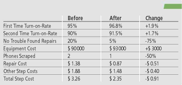
• Fixture improvements reduce NTF from 20 to 5%
The numbers in table 2 reflect the before and after states for the NTF (no trouble found) change from 20% to 5% which is the result of less „false“ failures by using a better fixture, and the turn-on-rates have also increased. In addition, scrap has been reduced because the probability of repeat failures has been greatly reduced. By saving $0.91 per unit and producing 300 per day, the result is a saving of $273 per day. The payback time for the better fixture is just 11 days. The saving of $0.91 is a 28% reduction in the cost of test. Over 50% of the saving is in the reduction of repair costs associated with less products being no-trouble-found failures
One last note of caution when designing a fixture: the testing needed to achieve the requirements for RF and audio environments can be difficult, time consuming and expensive. Also recommended is a repeatability studies for production tests to assure that the results are valid. In addition, the use of a comprehensive model to assess the real costs of test solutions is strongly encouraged.
ZUSAMMENFASSUNG
Für die Fertigungsprüfung von Kommunikations-geräten benötigt man sehr zuverlässige Adapter, um fehlerhafte Messungen weitgehend auszuschließen. Solche Adapter sind wegen der drahtlosen Analogtechnik der Prüfobjekte ziemlich komplex und erfordern höheren konstruktiven Aufwand, der sich jedoch auszahlt, weil damit weitgehend ausgeschlossen ist, daß gute Geräte als fehlerhaft klassifiziert und irrtümlich in die Reparaturschleife eingeschleust werden.
RÉSUMÉ
Le contrôle de la fabrication des appareils de communication nécessite des adaptateurs très fiables pour éviter autant que possible les erreurs de mesure. Ces adaptateurs sont assez complexes en raison de la technique analogique sans fil et impliquent une conception plus coûteuse qui se rentabilise cependant dans la mesure où elle permet d’exclure en grande partie que des appareils en ordre soient classés défectueux et amenés par erreur au circuit de réparation.
SOMMARIO
Per controllare le produzioni di apparecchi di comunicazione sono richiesti degli adattatori molto affidabili, per poter escludere ampiamente misurazioni erronee o falsificate. Simili adattatori sono alquanto complessi a causa della tecnica analogica senza fili e richiedono un dispendio maggiore dal punto di vista costruttivo, ma che viene ricompensato per il fatto di poter ampiamente escludere di classificare erronei gli apparecchi di buona qualità, con la conseguenza di introdurli erroneamente nelle attese di riparazione.
Share:


