Semiconductor manufacturers eager to adopt ’no-clean‘ techniques should nonetheless retain a cleaning step in their process for some products. It sounds counterintuitive that you would need to clean so-called no-clean materials. After all, the phrase no-clean gives hope that we can remove, or at least minimize, the cleaning process in a flip-chip line.
Michael Todd, Dexter Electronic Materials, CA, USA Mike Bixenman, Kyzen Corporation, Nashville, TN, USA
But in recent experiments by Dexter Electronic Materials and Kyzen Corp., we found evidence to support the need for cleaning ’no-clean‘ materials. Specifically, we found that in flip-chip packaging the companies can increase throughput, yield and performance when they integrate cleaning into their manufacturing process even when they use no-clean flux.
With the trend toward smaller assemblies and faster production runs, manufacturers clearly need help, which is why we conducted this series of experiments. Our goal was to help define optimal flux cleaning process parameters for high performance flip-chip manufacturing processes. In our study, we assembled, cleaned, tested and evaluated model flip-chip components. We also conducted side-by-side comparisons of the cleaning ingredients. These include three commercial no-clean flux formulations and two cleaning solvent chemistries.
Top concerns
One of the chief issues for semiconductor packagers when they’re selecting a soldered flip-chip interconnection system is reliability. Both mechanical fatigue and corrosion of the solder joint can significantly affect the performance of a solder-based interconnect system during service. The solder composition, the substrate and underfill materials, and the severity of the environmental exposure influence the relative kinetics of damage accumulation due to these phenomena.
One way to improve the reliability of flip-chip interconnect systems is to use underfills. These materials fill the gap between the chip and substrate around the solder joints, reducing the mechanical stresses imposed on the solder joint by different thermal expansion coefficients of different materials. High adhesion of the underfill material to the substrate and die is necessary to improve the reliability of the interconnect system.
Cleaning of course can help, but it can also hurt if done improperly. Flux removal techniques are commonly used in many electronics manufacturing and assembly processes as a means of assuring consistent material properties and improving product reliability. These cleaning techniques typically provide clean bonding surfaces for enhanced device reliability. In some cases, however, cleaning techniques used in flip-chip assembly processes result in a degradation of properties, including inconsistent underfill flow patterns, the generation of voids during underfill cure and poor interfacial bond strengths.
Several aspects of flip-chip flux cleaning processes have been shown to affect the performance of flip-chip underfill materials. Among these are the following:
• Flux residue chemistry – Flux residues may interfere with the flow of underfill encapsulants causing gross solder voids and premature failure of the solder connection. Furthermore, flux residues may chemically react with the underfill polymer causing a change in its mechanical and thermal properties.
• Cleaning solution chemistry – Cleaning chemistry left under the die due to the inability to properly rinse will likewiseinterfere with the flow of underfill encapsulants, which may cause gross solder voids and premature failure of the solder connection.
• Cleaning solution application technique and process parameters – Flip-chip die have a tight pitch, low stand-off and dense array of solder bumps, which make post-reflow cleaning of flux residues increasingly difficult. Four key variables (solution chemistry, time, temperature and impingement energy) must be understood to achieve a robust cleaning process.
• Rinse solution chemistry – Rinse medium must be soluble with the cleaning solution. Moisture left under die may be an important factor affecting thermal fatigue failures.
Experimental procedure
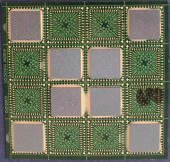
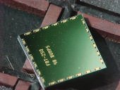
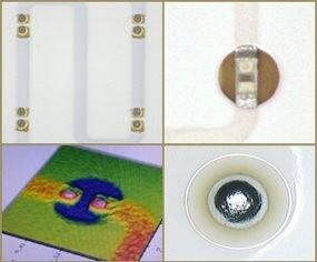
In conducting our experiments, we wanted to obtain results that applied to a broad segment of the industry, so we chose a fairly common test assembly consisting of a 35mm x 35mm FR4 laminate substrate having 16 flip-chip component sites (fig-ure 1). The substrate was 0.34mm thick laminate having Taiyo liquid photo-imagable soldermask defined gold plated conductor pads. The flip-chip components used in the study were Flip-Chip Technologies FB250 silicon nitride passivated die (see figure 2). These components have 48 peripheral eutectic solder bumps at a 0.46mm pitch.
The flip-chip dies were assembled using three no-clean flux formulations, two cleaning materials under a variety of conditions, and encapsulated using a commercial epoxy-based underfill material. These assemblies were evaluated for underfill flow defects including the presence of voids, filler striations and inhomogeneous contamination. The assemblies were then subjected to JEDEC level-3 preconditioning and pressure cooker exposure and evaluated for performance defects such as underfill delamination and cracking. Finally, the assemblies were subjected to pressure cooker accelerated testing (121°C, 100% relative humidity, 2.2 atmospheres of pressure) for 48 hours and evaluated for performance defects such as underfill delamination and cracking.
The dies were first placed bumps-down into a 0.0015-in thick bed of flux before placing them onto the substrate. The boards were reflowed with a peak temperature of 230°C. Two sets of soldere assemblies were set aside as control units.
The Accel system
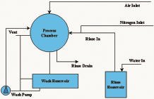
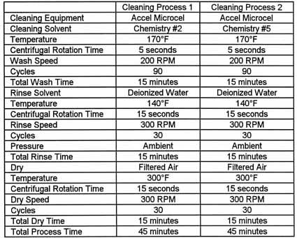
The Speedline Accel centrifugal cleaning system consists of a cleaning chamber, solvent reservoir, robot head and microprocessor-controlled system. The head automatically lowers the assemblies in a cassette into the cleaning chamber and seals the chamber from the surrounding atmosphere. The cleaning solution is automatically pumped from the storage reservoir into the cleaning chamber, submerging the cassette, and the control program rotates the assemblies in the solution. The cassette rotates in one direction, then reverse in the opposite di-rection. This rotation and reversal conti-nue during the wash cycle. Followinginitial wash, the cleaning solution re-turns to the reservoir, and a rinse cyclebegins.
With the cleaning chamber still sealed, de-ionized water is sprayed across the flip-chip assemblies. The centrifugal action allows the rinse water to penetrate under the die. After the rinse, the flip-chip assemblies continue to rotate while hot air is introduced to speed the drying process. The flow diagram of this process is shown in figure 3.
After cleaning, the test assemblies were then warmed to 90°C and underfilled using Dexter Hyso FP4549 which is an epoxy-based, low stress underfill material for use on semi-rigid and flexible sub-strate materials. The underfill was cured for 30 minutes at 165°C in a forced-air oven and then evaluated for evidence of flow-induced voids, filler striations and incomplete fillets by acoustic microscopy using a Sonoscan.
The parts were then subjected to JEDEC level-3 preconditioning consisting of unbiased environmental soak for 192 hours at 30°C and 60% RH, followed by three passes through a reflow oven with a peak temperature of 240°C/5°C. The assemblies were again evaluated by acoustic microscopy for evidence of delamination and cracks. Finally, the parts were subjected to pressure cooker accelerated testingat 121°C, 100% RH and 2.2 atmospheres of pressure for 48 hours. The assemblies were again evaluated by acoustic microscopy.
Experimental results
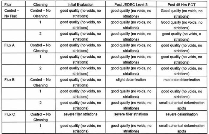
Table 1 summarizes the test results of this investigation. Acoustic microscopy analysis of the flip-chip samples showed minimal evidence of delamination, cracking or voids created as a result of the JEDEC level-3 preconditioning process. This segment of the evaluation, therefore, created negligible differentiation in performance between the control samples contaminated with flux residue and the samples treated with each of the cleaning processes. Acoustic microscopy analysis of the assemblies after48 hours exposure to pressure cooker conditions, however, show dramatic stress related delamination at the die-to-underfill interface.
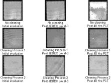
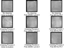
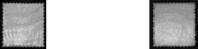
Figure 4 illustrates the effects of a cleaning process on the flow performance of the underfill material on the flip-chip devices. Die #1 is an acoustic microscopy image of a sample device assembled using flux C without a cleaning process. This figure shows distinct flow striations along the dispensed edge of the die. These striations in the underfill material represent density variations caused by irregular flow rates beneath the chip. Die #2 is an image of a similar flip-chip device assembled using flux C and cleaned using process 1 prior to the underfill. This image exhibits only slight density variations indicating a marked improvement over the sample without the cleaning process. Figures 5 and 6 show images of the flip-chip test devices for flux B and C material process combination. Bright white areas of the acoustic microscopy images represent areas of delamination or voids. Dark black spots along the edges of each of these images are the peripheral solder bumps.
Cleaning still has a place
Test data indicates that flux residues under flip-chip dies may affect the flow of underfill materials resulting in striations and voids. Furthermore, if subjected to severe environmental conditioning, flux-contaminated flip-chips may prematurely fail due to interfacial delamination. Control flip-chip devices assembled using no flux showed no signs of voids, striations or delamination after environmental testing. Likewise, test devices assembled using flux A showed no indications of voids, striations or delamination after environmental testing. Test devices assembled using flux B and C, however, contained flow induced failures including voids and severe striations as well as environmental stress related delamination failures.
Clearly, flux A provided the most robust flip-chip assembly for the test conditions evaluated. Flux A has very low solids that result in a very low residual contamination beneath the die. We can ask, why not select flux A or use no flux in the assembly of these devices to maximize performance? The answer is, the soldering assembly yields and solder joint integrity relies on the activity of the flux. Flux A has lower activity than the other fluxes evaluated. In some cases, this flux may provide inadequate fluxing activity to create high performance solder joints.
Both fluxes B and C are higher activity formulations that leave behind higher levels of residue. As a result, there are voids, flow striations and delamination on control samples in which no cleaning was performed. Cleaning processes 1 and 2 (table 2) dramatically improved the underfill flow performance and flip-chip mechanical stability of test devices assembled using flux B and C without causing negative effects to these devices. These cleaning processes appear to provide ideal surfaces after cleaning for optimal underfill performance beneath a soldered flip-chip device. Cleaning processes 1 and 2 consistently provided the good surface for bonding. These procedures removed enough residues from fluxes A and B to provide excellent reliability through JEDEC level-3 preconditioning and 48 hours PCT exposure. Furthermore, these cleaning processes did not degrade the performance of the devices in any way. The results in favor of cleaning are a bit surprising given the trend toward no-clean manufacturing. However, as the industry evaluates no-clean fluxes and other advances in flip-chip assembly, it’s evident that cleaning still has a place in semiconductor packaging.
Acknowledgments
The authors would like to thank Ms. Kathy Costello, Dexter Electronic Materials and Mr. Erik Miller, Kyzen Corporation for their contributions to this investigation, also the Deflex Corporation for their cleaning using the Superfuge system. This article is based on a paper presented at Apex 2000.
Zusammenfassung
Im Packaging von Flip-Chips erbringt selbst bei Anwendung von No-Clean-Flußmitteln beim Herstellen gelöteter Interconnects die Reinigung der Chips erhebliche Verbesserungen in Prozeß und Ausbeute. In einer Studie wurde nun festgestellt, welche Flußmittel-Reinigungsprozeduren nötig sind, damit optimale Prozeßkonditionen sichergestellt sind.
Résumé
Dans le conditionnement des Flip-Chips, le nettoyage des puces améliore sensiblement le processus et le rendement, même en cas d’utilisation de fondant No-Clean pour la réalisation d’interconnexions brasées. Une étude a révélé quelles procédures de nettoyage du fondant étaient nécessaires pour assurer des conditions de fabrication optimales.
Sommario
Nel Packaging di Flip-Chips e durante la realizzazione di interconnects saldati a dolce la pulizia dei chips comporta un notevole miglioramento sia nel processo che nella resa, anche se vengono usate sostanze diluenti di tipo No-Clean. In una analisi effettuata sono state determinate le procedure di pulizia e le sostanze diluenti necessarie al fine di garantire condizioni di processo ottimali.
Die#1:Flux C without cleaning
Die#2:Flux C without cleaning Process 1
Share:


