In-line board assembly inspection in a high-volume manufacturing environment can be very challenging. AOI systems can be used to improve quality and reduce defects, but frequently result in production bottlenecks due to excessive false calls. As an alternative to camera-based 2D AOI systems, 3D laser scanning can generate synthetic images greatly reducing the number of false calls, as those systems are not sensitive to color or brightness variations.
Carl Pollard, GSI Lumonics
For any AOI system to be a useful addition to a production line, it has to be capable of accommodating all the normal process variations, such as changes of vendors or delivery of PCBs and other parts or solder masks, etc. Many 2D systems struggle to cope with such a wide variation in visual information. The majority rely on complicated algorithms which could be several pages long to try and overcome this problem. When a slightly different part is introduced, most systems need some sort of algorithm adjustment. Constant algorithm adjustments can have the negative effect of widening the range of what can be accepted as good by the system. Inspecting an unpopulated but solder-pasted board can be quite revealing after a system has been in use for some time, and many algorithm changes have been made to accommodate the constant variation in inspection data.
False calls and false accepts can be quite time-consuming to rectify, particularly if there are multiple systems and programs which are not transferable to other inspection equipment. Although careful algorithm tuning can help minimize the problems, it can appear to be a never-ending and too time-consuming task.
Suppliers of AOI equipment often quote very low false-call rates. However, little is said of false accept rates or the training level of the staff required to obtain those good results, and the amount of time required to keep the system running at those outstanding levels. There is no doubt that most systems can be made to run very well; the question to be asked is how much work is involved in getting to that point, and what do you need to do to keep the systems running at that exceptional level.
There have been many articles written about where AOI should be placed in the production line, but detecting faults as they occur and improving the process to prevent the same faults again is the correct way to proceed. Besides the systems targeting the paste printing process where more than 50% of the end-of-line defects occur, component placement inspection (CPI) has always been the second most important area to reduce rework and scrap.
3D component inspection is a very effective option. Variations in board or part color have little affect on the inspection; this removes one of the biggest hurdles the 2D systems have to overcome. Program portability is a problem to many 2D systems; minute changes in lighting and camera calibration have a large affect on the inspection result. Some 2D systems may require substantial changes to their databases or new algorithms – creating, in effect, the necessity of having to re-write the same program for each machine, or re-writing all programs after camera change or adjustment. This is not a problem with a 3D system. Part size will not vary from system to system, and there are no lighting parameters to adjust. A component placement inspection system uses the same patented 3D-scanning laser technology that is used in 3D laser paste inspection. The only difference between both machins is the additional software which includes component algorithms, programmable Z-resolution and enhanced image processing capability. 2D and 3D data are analyzed simultaneously.
The software identifies the top of the part and then measures down towards the board. A horizontal section is then taken at that point, and the area of the part measured, board warpage, color of components or board have little effect. Parts are judged on area, XY and theta position. Moreover, misplaced or wrong-sized or tombstoned/ billboarded components, parts on side, upside down SOTs and diodes are identified. Additional algorithms check polarity in both 2D and 3D. Leaded devices can be verified by looking at the meniscus or feet on the solder joint. Corner and side algorithms are used for advanced packages, large parts such as QFPs and odd-shaped parts.
Experience in real processes
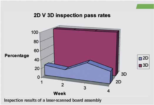
Recent evaluation at a European OEM proved that a 3D system with laser-scanning technology provided considerably fewer false calls than a 2D only system. This company had an operator initially reviewing the defects from the existing AOI; each false call had to be checked. The line with the 3D system had a very low number of false calls (under 10 PPMO), false accept rates have been found to be close to zero. The operator could then be released from this point in the line in order to attend to other equipment in the line.
The system can be configured in a number of ways. At one evaluation site, operators can be alerted by an audible alarm when a fault is detected. The machine holds the board inside, and the operator reviews the fault in real time. Once reviewed, the board is ejected from the machine and the fault rectified, problems being fixed as they occur.
If the same fault is seen 2 or 3-times, the operator can easily recognize that something is wrong with the process, and the defect source identifier helps pinpointing which machine, feeder or placement head are causing problems. Faults are rectified without building incorrect boards and creating rework backlogs. Has a typical defect been detected by post-reflow AOI gear, potentially 40 or 50 boards would require rework. Therefore, detecting a fault and its source so quickly reduces cost.
The 3D scanner technology has been around for some time now and has proved to be extremely reliable and robust. It has no moving delicate parts and it requires no routine maintenance or frequent part replacement. The cycle time for a system to carry out 100% inspection on a typical high-density board assembly (140 x 210mm) is around 25s. The inspection time is governed by area, and not component density or component count as some others systems are. This scanning system can inspect practically any part down to 0201s. Component placement inspection is simple to use and a reliable process which doesn’t need valuable engineering resources to keep running. Using 3D laser technology can significantly reduce the number of false calls and accepts, leading to increase in yield and improvement in quality.
ZUSAMMENFASSUNG
Auf der Basis von Laser-Scanning lassen sich sehr schnell in der Fertigungslinie die auf Baugruppen plazierten Bauteile noch vor dem Lötvorgang sehr genau kontrollieren. Solche Systeme liefern 2/3D Abbildungen und sind nach Anbieteraussage nicht „farbenblind“, haben also keine Probleme bei der Umsetzung von unterschiedlichen Farben gleicher Sättigung und identischem Kontrast.
RÉSUMÉ
Le scanning laser permet de contrôler très rapidement et avec une grande précision avant le brasage les composants déjà placés sur les modules dans la ligne de fabrication. Ces systèmes fournissent des représentations en 2/3 D et, d’après les fabricants, reconnaissent les couleurs. Ils n’ont donc pas de problème à convertir des couleurs différentes de même saturation et de contraste identique.
SOMMARIO
Con lo scansionamento laser è possibile controllare in maniera molto precisa i componenti piazzati sui gruppi costruttivi all’interno della linea di produzione, ancor prima che essi vengano saldati. Tali sistemi forniscono immagini bi- o tridimensionali e a detta dei produttori non sono soggetti a „daltonismo“, vale a dire che non hanno problemi nel riconoscimento di differenti colori con identici valori di saturazione e di contrasto.
Share:


