As experiments show, the squeegee pressure exerted during printing is not distributed over a large percentage of the board surface area. A region extending around 25mm either side of the squeegee blade bears the main proportion of this pressure. The forces exerted are high enough to risk damage to component leads and bodies. Component support must be more densely nested to protect delicate I/Os from damage.
Component damage caused by mechanical over-stress during screen printing is a little-understood phenomenon. The pressure exerted on components is already greater than many manufacturers and component vendors have anticipated. While most analysis of the stresses encountered with pin-type tooling assumes that pressure is distributed widely across the underside of the board, analysis shows that the squeegee pressure exerted during printing is actually concentrated in a relatively small region around the squeegee blade. Low PCB rigidity – due to the use of thin-gauge FR4 materials or other processes such as routing – is the main reason for this concentration of forces, which leads to increased stress. This brings a high risk of component damage, including deformed, broken or shorted leads, as well as the potential for damage or perforations in the outer packaging of components such as chip-type resistors and capacitors.
Next generation conformable tooling
Conformable tooling pin arrays make contact with underside components to maximise board support during screen printing. This technique has successfully improved paste volume transfer and accurate paste-on-pad deposition for high-density assemblies. Although users have assumed that the squeegee pressure exerted during printing is distributed over a large percentage of the board surface area, experiments performed using modern thin-gauge PCBs show the area to be rather smaller in practice. A region extending around 25mm either side of the squeegee blade bears the main proportion of this pressure. The forces exerted are high enough to risk damage to component leads and bodies.
New materials allow a next-generation conformable tooling that distributes the forces more evenly throughout this narrow region either side of the squeegee, to reduce the stresses imposed on individual components.
Stable tooling is important because poor board support is the single greatest enemy of repeatability in screen printing processes. Recently, pin-array tooling for screen printing has evolved to allow contact with underside components. The main goal has been to ensure adequate support for densely populated boards, where there is insufficient access to the board surface for conventional tooling pins or traditional milled plates with pocket reliefs.
When using a conforming tooling-pin array, the printer squeegee force is assumed to be distributed across a large number of pins in contact with many devices. Manufacturers feel assured that individual components do not experience excessive stress. However as typical PCB thicknesses are reduced to save cost and size, there is an accompanying loss of rigidity in the board, which tends to concentrate squeegee forces within a smaller area. As a result, the pressure exerted on the body or leads of an individual component can be higher than engineers may think. Moreover, only a portion of the tooling pin face may be in contact with the component, thereby further increasing the stress placed on the component.
New research shows that these forces can be significantly higher than manufacturers, tooling vendors or component suppliers may expect.
Distribution of squeegee pressure
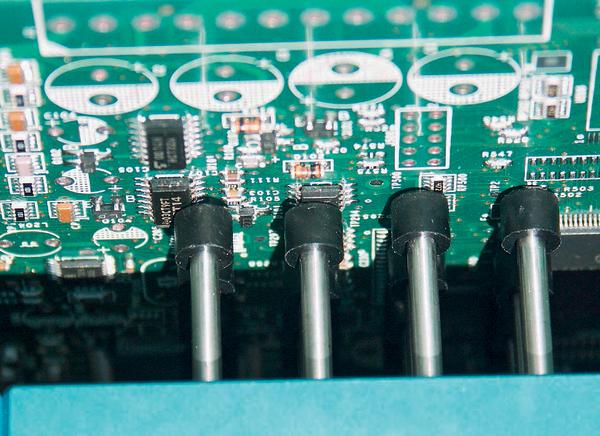
When a tooling pin array is brought into contact with the underside of an assembly, the contact force is usually accepted to be only a few grammes per pin; typically around five grammes. However, in most systems the pins are locked after the tooling pin array has conformed to the topology of the assembly. Hence when printing commences, the force exerted on underside-mounted components is then determined according to the squeegee pressure applied. The following expression describes the pressure exerted by the face of the pin as it bears upon a component.
This expression recognises the fact that a given pin may not be in full contact with the component body or I/O. Clearly if a pin is only partially in contact – perhaps touching only the edge of a package or a section of a component lead – the pressure exerted at that point will be correspondingly larger than if the entire surface of the pin had been in contact. With this in mind, Novatec set out to examine the behaviour of modern 1 mm-gauge FR4 printed circuit boards by setting up an experiment to understand how the squeegee pressure is distributed and subsequently to quantify the stresses thus imposed on underside-mounted components. The test assembly was a double-sided PCB supported using a standard configurable-pin tooling array featuring pins on a 1-inch (25.4mm) pitch.
Majority of squeegee pressure is concentrated
A practical setting for squeegee pressure in a typical volume-production process may be around 10kg. Process engineers and tooling vendors assume that this force is distributed evenly across the majority of the total PCB surface area. However, strain-gauge data recorded from the test assembly during this experiment showed that the majority of the squeegee pressure is concentrated within an area around 25mm either side of the squeegee blade. Hence, for tooling systems based on a 1-inch pin pitch, a single row of pins may bear almost the entire squeegee force as the blade traverses. Combining this observation with the experimental settings as described, the expression can be written:
where:10000g is the squeegee force; 25mm is the distance over which the squeegee pressure is distributed; 200mm is the total length of the PCB.
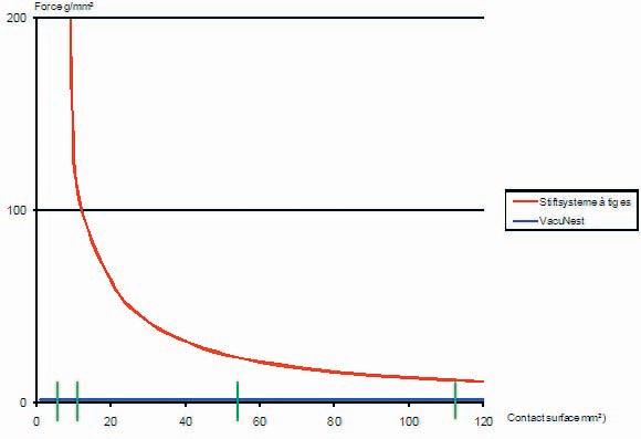
Given that the diameter of the pin face is 6mm, the maximum surface area in contact with any given component is 13mm2. Hence assuming full contact between the pin and the component, the pressure exerted at each point is 11g/mm2. If the pin is only partially in contact, however, the pressure exerted increases rapidly.
Forces of this magnitude – exerted on the gull-wing I/Os of a Plastic Quad Flat Pack (PQFP) component, for example – are capable of distorting the I/Os sufficiently to promote failures at visual inspection or to induce defects such as shorted or broken leads. The component body may also become damaged if excessive pressure is exerted within a small contact area.
Backside components under stress
Many manufacturers will be surprised to learn that components are experiencing stress of this magnitude during screen printing. Moreover, these stresses are significantly greater than the maximum pressure recommended by component manufacturers.
The pressure exerted at any given point due to squeegee forces can be lessened if more contact points are introduced. One way to achieve this may be to reduce the pitch of the tooling pins. On the other hand a custom tooling plate, optimised to make contact over the entire surface of components such as smaller chip devices as well as large semiconductor devices, can distribute squeegee force over many contact points within the 25mm area around the squeegee. But, as mentioned earlier, densely populated bottom side assemblies do not offer enough bare board surface area to support.
Alternative: Spreading the load
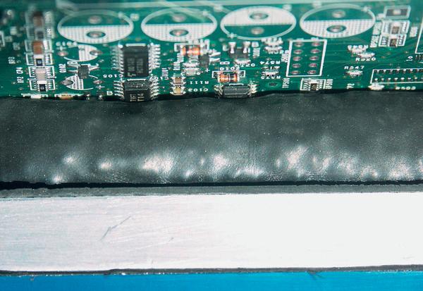
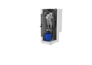
As an alternative, modern materials technologies enable configurable tooling that can also provide fully distributed support, e.g. a tooling module containing a foam former surrounded by polymer granules. During setup, using a reference assembly and a tooling plate placed above to ensure flatness and coplanarity, the module conforms to match the underside contours of any given assembly. This shape can then be locked using a vacuum, and thereby retained throughout processing of subsequent production units. The flat plate used for tooling set up helps to remove the influence of any bow or warpage of the board. Subsequent production units, if bowed, will be flattened by squeegee action to match the initial reference setup, thereby enhancing coplanarity between the squeegee, stencil, and board to promote better gasketing, paste volume transfer efficiency, and process repeatability (Cpk).
By ensuring many more points of contact between the tooling support and the underside of the assembly, the high point-force pressures exerted at the faces of individual tooling pins are eliminated. Instead, the force due to squeegee pressure is distributed more evenly throughout the area around the squeegee.
Analysing the distribution of forces during printing, using the same expression as before, a value for the pressure exerted can be calculated:
Hence the pressure experienced by the components in contact with the tooling is around one tenth of the minimum pressure exerted by a conforming pin array. Compared to those cases where only a portion of the surface of any given pin is in contact with the component, the reduction in pressure achieved by using compliant foam/polymer tooling is significantly greater.
Practical analysis of the performance of this type of tooling demonstrates consistent board support capable of sustaining wet print height Cpk close to 2.0. SPC results for a batch of 15 test assemblies, processed under the same conditions as described earlier and the paste sites from which SPC data was collected demonstrate that stable support can be established anywhere on the surface of the board, resulting in consistently high Cpk.
With further decreases in PCB gauge, and as component spacing on dense double-sided assemblies continues to reduce in relation to the relatively large pitch of conforming-pin array tooling modules, the stress on components can be expected to increase steadily.
Conformal tooling capable of distributing printing forces over many more points of contact within the main load-bearing zone around the squeegee promises to reduce these stresses, with potential benefits for end-of-line yield as well as field reliability.
epppe409
Mapping stresses with pressure sensitive film
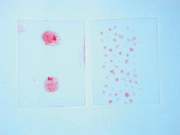
Pressurex pressure sensitive film provides a convenient means to measure the distribution and magnitude of pressure between two contacting surfaces. A film is placed between the two surfaces, which are then brought into contact. As pressure is applied, microcapsules contained within the mylar film rupture and produce an image mapping pressure variations across the contact area. The intensity of the colour is directly related to the magnitude of the pressure applied; the greater the pressure, the more intense the colour.
The images shown on the right side compare pressure maps for conventional conformable pin array tooling and VacuNest. The VacuNest map displays many more contact points, with close matching of the pressures experienced at all points. The dark points on the pin-array map confirm that underside-mounted components experience much higher peak pressures as the printer squeegee passes.
Zusammenfassung
Wird nach fertiggestellter Baugruppen-Unterseite die Oberseite mit Lötpaste bedruckt, wird bei herkömmlichen Haltevorrichtungen die Anpresskraft des Rakels nicht wie bisher angenommen breit verteilt. Einzelne Bauteile der Unterseite können mit Kräften belastet werden, die das Bauteil selbst oder die gerade erst hergestellte Lötverbindung nachhaltig beeinträchtigen. Präzisere Anpassung der Haltevorrichtung an die geometrischen Gegebenheiten der Board-Unterseite ist notwendig.
Si la face supérieure du composant est imprimée avec de la pâte à braser une fois la face inférieure terminée, la force de pression de la racle n’est pas répartie sur la largeur comme supposé jusqu’à présent avec les dispositifs de maintien traditionnels. Les différents composants de la face inférieure peuvent supporter des forces qui risquent d’endommager durablement le composant ou la liaison soudée qui vient d’être réalisée. Une adaptation plus précise du dispositif de maintien aux données géométriques de la face inférieure de la carte est nécessaire.
Share:


