The preceding paper contained a detailed description of the patented Bond Process Control (BPC) system. It monitors and regulates the amount of ultrasonic energy applied to the bond by following the wire deformation while bonding, because the small variations in surface properties require different optimum ultrasonic energy. This improves the bond results. An extension of this process is described in this paper, i.e. monitoring the transducer impedance during the bond process. This development has been patented in the US and Europe.
By Dr. Farhad Farassat and Dr. Josef Sedlmair, F&K Delvotec, Ottobrunn/Germany
The BPC unit continuously monitors how the bonding wire’s deformation during bonding and controls the ultrasonic power setting accordingly, so as to maintain a constant deformation speed. This requires, however, that there exists a wire deformation to be monitored: in the usual wire-bonding processes at room temperature, the deformation phase proper is preceded by a cleaning phase. During this phase the ultrasonic energy is mostly consumed by rubbing the bonding surfaces against each other and cleaning them in this fashion. For this reason, no discernible deformation develops during this phase which normally lasts only a few milliseconds. The ultrasonic control system slowly ramps up the energy until wire deformation becomes observable.
During this “silent“ phase – as regards wire deformation – there are, nonetheless, some parameters which are useful to measure. In practice it is well known that (especially for some metal pairings) even the very first milliseconds of bonding, i. e. well before an observable wire deformation appears, can be crucial for the quality of the bond being formed. This is the case for bonding surfaces which are particularly sensitive to the so-called “coupling” of the ultrasonic energy, for instance highly sensitive types of metallization.
This “coupling” refers to the transfer of the transducer oscillation with its typical amplitude of a few micrometers from the bond wedge to the bond wire situated under the wedge. If this coupling action does not take place fast and reproducibly, then the bonding surfaces are in danger of grinding against each other, or even of smoothing each other. In extreme cases the metallization may even be rubbed off the surface completely before a bond is formed. Another risk is that the bond wedge’s touchdown on the bonding surface already pre-deforms the wire to such a degree that further deformation for bonding cannot take place, again resulting in a bad bond.
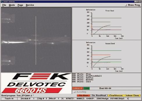
One parameter which can easily be measured is the impedance of the transducer during the bond process. This impedance is altered by the variable damping of the mechanical oscillator by the bonding site itself. This transducer impedance correlates quite well with the oscillation amplitude at the tool tip, and it can be measured simply and precisely. The oscillation amplitude, in turn, evolves in a characteristic fashion during the bond process. The image down shows the screen of a typical heavy wire bonder during bonding. The right-hand half of the screen displays monitoring windows for the first and the second bonds. The wire deformation curves are clearly visible; they have been discussed at length in the previous paper.
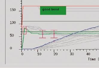
The graph aside above shows a section from this monitor image and displays in blue the well-known deformation curve against the bond time (bond time units are milliseconds). The Y axis is calibrated in arbitrary, non-dimensioned units. Above the deformation curves, a typical impedance curve is shown in green, and above it, in red, the normal ultrasonic energy curve. After touchdown of the bond tool (time t is equal 0 ms), the ultrasonic energy is turned on and the voltage applied to the transducer rises rapidly to the set value. The impedance (in green) follows with a delay of a few milliseconds, characteristic for the individual system, and indicates a maximum oscillation amplitude at the tool tip.
After a very short interval the mechanical contact of the two bonding surfaces (wire and bond pad) is established and damps the oscillation at the bond tool. This can be observed by the decrease in oscillation amplitude (and change in impedance). In the case shown in the image left, this damping effect takes place within around 4 ms, which corresponds to 250 to 300 oscillations for an ultrasonic system of 60 kHz. This is a typical practical case and was also used here.
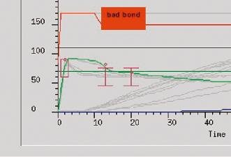
For each combination of materials (e.g. aluminum wire on a nickel bond-pad), the speed and degree of damping is characteristic. Under constant conditions, such as clean and rigidly mounted surfaces, these damping curves are highly reproducible and therefore are a good indicator of how well the bond is developing. Needless to say, this can also easily be observed in the subsequent development of the wire deformation itself. If the conditions are sub-optimum, this is often due to contaminations on the bond surfaces. The most frequent are ones which leave lubricating coatings which sharply reduce the friction of the bonding partners. This is immediately obvious in the coupling of the ultrasonic oscillation, as shown in the graph aside below: there, a small amount of contaminant was added purposely, and the ultrasonic action takes around 10 ms to remove it. During this time the damping of the oscillation is smaller and therefore the green curve drops more slowly. The oscillation couples are not as well also evident in the subsequent poorer wire deformation which, in this case, was purposely not compensated by the BPC in order to show the effect more clearly.
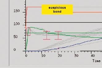
If the contamination is still worse, as the example shows in the graph aside middle, the bond wedge oscillation is damped even more weakly, and the green curve decreases even more slowly. As expected, this results in a very poor (or even missing) wire deformation because the ultrasonic oscillation is now transmitted so poorly that it is no longer able to generate the necessary friction of wire to bond-pad, as can be seen in the flat blue deformation curve. In these latter two cases, the variation in development of the transducer impedance already indicates a problem bond.
In general, the user has the choice of utilizing this impedance check in one of two ways: either as a mere monitoring and supervision system, or as a warning device which stops the bonder if certain types of curves occur. In the latter mode, thresholds can be set at several freely chosen points along the bond process. In the figures shown above, they are indicated as violet bars at 2, 13 and 20 milliseconds. For a “good” bond it is required that the impedance curve pass through all three windows. If it touches the margin at one or several windows, the bond can be marked as suspicious, and if one or several bars are missed altogether, a bad bond can be assumed.
For heavy wires the bond-head itself can be equipped with a pull test unit which selectively pulls such wires destructively or non-destructively; in addition, all types of bonders can report such bonds to a host computer system in order to flag them for later visual inspection, manual repair or disposal. The capability of this checking device notwithstanding, it is important to note that the typical curve shape depends strongly on the particular combination of bonding materials. The results described above, for instance, were generated on rather smooth materials. There the initial damping of the ultrasonic amplitude does not appear until after a few hundred oscillations. In contrast, customary leadframe materials show a more constant damping because of their greater roughness. In practice it has proven useful to use the impedance check mainly to monitor the uniformity of surfaces and materials within a lot, and also from one lot to another. For this purpose one only needs to observe how uniformly the impedance curves are compared one to another, and whether they keep their shape and position at a change of lots or if there is a change. To assist this quick visual check, the bonder displays on the screen the current curve in color and all preceding curves in grey. This feature permits a very simple bond test or incoming inspection of new lots, or also of samples from new suppliers.
Combined with the BPC which can run simultaneously, the pull-tester integrated in the bond head and the subsequent optical Post-Bond-Inspection (PBI), the impedance check completes a whole range of powerful capabilities to produce at highest quality levels and to avoid mistakes not retroactively by rejecting the part but a long time in advance: by compensating process changes and drifts as soon as they are recognized. At the same time, these methods permit vastly improved control and documentation of the manufacturing process. Especially for high-performance components and for demanding customers, this is a crucial competitive advantage for a high-cost production region like Europe.
EPP EUROPE 433
Zero Defect Production – Series Overview
Part I: Precise Control and Verification Procedure
EPP Europe 09/10 2005, page 54–55
Part II: Sophisticated Post-Wire Bond Inspection
EPP Europe 11/12 2005, page 78–79
Part III: Effective Die Post-Bond Checking
EPP Europe 01/02 2006, page 38–39
Part IV: Bond Process Control of Wire Bonds
EPP Europe 03/04 2006, page 36–37
Part V: Impedance Check for Wire-Bonding
EPP Europe 05/06 2006, page 48–49
Zusammenfassung
Der fünfte Teil dieser Reihe über Null-Fehler-Produktion beschreibt eine Erweiterung des Verfahrens der Bondprozesskontrolle. Der Beitrag erläutert die Verfolgung und Analyse der Transducer-Impedanz während des Bondvorgangs. Dieses Verfahren ist in Europa und in den USA patentiert unter EP 1343201 und US 6912906. Die Bondprozesskontrolle überwacht laufend die Deformation des Bonddrahts während des Bondens und regelt in Abhängigkeit davon die Ultraschall-Leistung. Die Ultraschall-Energie wird verwendet, um die Bondoberflächen über ein Aneinanderreiben zu reinigen.
résumé
La cinquième partie de cette série concernant la production zéro-défaut décrit une extension de la méthode de contrôle de la connectique filaire. L’article explique le suivi et l’analyse de l’impédance du transducteur pendant l’opération de connectique filaire. Ce procédé est breveté en Europe et aux USA sous le n° EP 1343201 et US 6912906. Le contrôle de la connectique filaire surveille en permanence la déformation du fil pendant l’opération et règle les ultrasons en conséquence. L’énergie ultrasons est utilisée pour nettoyer les surfaces en les frottant.
La quinta parte di questa serie sulla produzione priva di errori descrive un ampliamento della procedura del controllo del processo di microsaldatura. Il contributo spiega il puntamento e l’analisi dell’impedenza del trasduttore durante il processo di microsaldatura. Questo processo è brevettato in Europa e negli USA con i numeri EP 1343201 e US 6912906. Il controllo del processo di microsaldatura controlla costantemente la deformazione del filo durante la saldatura e regola di conseguenza la potenza degli ultrasuoni. L’energia a ultrasuoni viene utilizzata per pulire le superfici di saldatura tramite uno strofinamento.
Share:


