When reworking lead-free assemblies greater care is required to prevent higher process temperatures, necessary for reflow, from damaging adjacent components and other solder joints in the rework area, including the backside of the board. At the same time, operators are under pressure to maintain or increase productivity; process-control improvements must be achieved without reducing throughput. If throughput is to be maintained or increased then with hot air or even IR rework systems, the rate of temperature increase (ramp rate) must be higher to reach the higher lead-free reflow temperatures within the same time period.
A number of changes have come about as a result of the transition from tin-lead (SnPb) to lead-free soldering processes. Sn63Pb37 solder melts at 183 ºC and requires a peak reflow soldering temperature between 210 to 220 ºC for an acceptable solder joint to form. With widespread understanding of hand soldering processes, reworking of SnPb assemblies has become relatively straightforward and often taken for granted. However, the same cannot be said of lead-free rework. The most popular lead-free tin-silver-copper (SAC) solder alloys have a melting point range of 217 to 221 ºC, fully 30 to 40 ºC higher than lead-alloy solders. Lead-free solders require peak reflow soldering temperatures between 235 ºC and 250 ºC. These higher temperatures, in turn, place a demand for better process control than for SnPb solders, to prevent thermal damage to components from excessive heating. Therefore, the lead-free soldering process window will be much smaller than for SnPb solders. These and related issues involved in producing high-quality lead-free rework are often not fully understood. On the whole, quality must be engineered into a lead-free rework process.
Collateral damage
One of the most important issues to understand is that the higher soldering temperatures that must be applied for lead-free processes have the potential to affect adjacent components, including those on the underside of the board. Where components are located beneath, say, a large top-side mounted BGA – which has a high thermal capacity – the energy required to desolder or reflow the BGA may also cause the underside solder joints to partially or fully melt. Small passive surface-mount devices are particularly vulnerable, since their solder joints have a low thermal mass and can quickly melt before the higher mass top-side component is reflowed. In all cases, it is well documented that solder joint and pad-to-board integrity become compromised with repeated reflow exposure. Other components at risk include devices with plastic bodies such as connectors, which can melt or become deformed by excessive heat. To establish a high-quality lead-free reflow process, measures must be in place to protect these joints and components, and prevent them from reaching excessive temperatures.
Care must also be taken to ensure that these sites are inspected after the rework activity is complete, to verify that they have not been damaged. It is surprising how often this important precaution is not taken. Industry standards, such as IPC-A-610D, Acceptability of Electronic Assemblies, and IPC J-STD-001D, Requirements for Soldered Electrical and Electronic Assemblies, provide the inspection criteria for lead-free solder joints.
Reworking array packages
Industry consensus has established that the preferred method for reworking BGA devices, including desoldering and reattaching the device, is a convection-based hot-air array-package rework system. Invariably, the system should have closed-loop control of time, temperature and airflow parameters. With these controls, users can establish thermal profiles. This allows the preheat, soak, ramp, reflow and cooling stages of the reflow profile to be optimized for a given application.
The major challenge for an array-package rework system is to manage the delivery of heat within a prescribed period of time to the desired rework site without either damaging the component being reworked or, as mentioned, causing adjacent components to become reflowed, detached or damaged. The IPC recommends a maximum temperature of 260 ºC for the lid and body of plastic components. However, opinion varies within the industry, with some component manufacturers recommending a lower maximum of 250 °C. In Japan, component manufacturers and assemblers alike limit the peak temperature of 245 ºC as being a more appropriate maximum. Since these temperatures are extremely close to the reflow temperature of SAC solder alloys, any rework system must manage peak temperatures extremely closely.
Under these constraints, the distance between the nozzle with hot air output and the connections being reflowed becomes an important parameter. If the nozzle-to-PCB distance changes the profile can be affected by 10 °C or more. Thus PCB warping during heating can, for example, affect the repeatability of the rework process. While it is undesirable when reworking a SnPb assembly, this is unacceptable with lead-free processes given their much smaller process windows. Therefore it is important that the nozzle-to-PCB distance be established when setting up a process.
Moreover, where lower temperature SnPb BGA rework processes could be reworked without the need to support the board assemblies, in higher temperature Pb-free processes a board support is considered necessary to prevent PCB warping and thereby help to maintain a consistent nozzle-to-board distance. This is necessary because boards are more prone to warping in a lead-free process, since the output temperature tends to ramp more quickly and board temperatures reach significantly above the glass transition temperature of the PCB (typically 135 °C to 150 °C for FR4 material) for longer periods. In the future, changing the board material to a medium having a higher glass transition temperature will reduce the probability of PCB warping.
Equipment requirements
When considering the profiling strategy, the most important objective is to prevent overheating of the board and components. There is no value in repairing one area of the assembly if the PCB under-side or other areas become degraded through excessive or uncontrolled heating. As we have established, the two requirements for reworking lead-free double-sided assemblies are higher peak temperatures with increasing levels of temperature control. This means that rework equipment must be able to support temperatures up to 700 °F (371 °C). This not only applies to array-package rework systems, but also to conduction soldering systems that may be used for touch-up on the board underside of the BGA being reworked. Even more, soldering systems should not overshoot their temperature set-point. Clearly, selection of consumables such as solder wire, solder paste, solder wick, solder fluxes, and cleaning solvents must also be adjusted.
Rework processes will greatly benefit with the application of under-board heating which helps prevent PCB warping and provides added thermal capacity where the latter significant for profiles with small process windows. When under-board heating is combined with top-side heating the temperature of the board can be raised to a point just below the solder reflow temperature. Once this occurs, the top-side nozzle can complete the heating process and at lower reflow temperatures due to the added thermal capacity from the bottom heater. Potentially problematic thermal deltas and shock to the board can be eliminated.
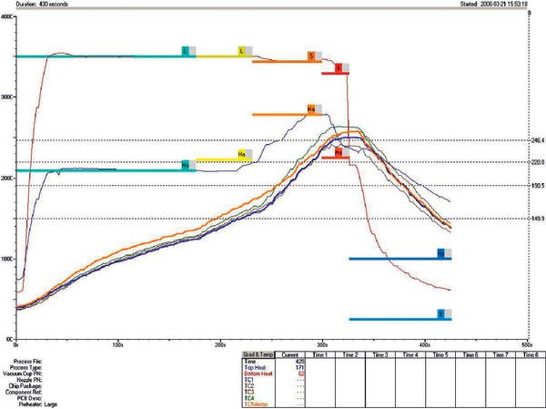
For even better process control with lead-free processes, the most successful rework systems now include dual-stage, convection bottom-side-heaters. This enhancement adds capability for achieving focused heating directly beneath the rework site. Concurrently, it keeps adjacent components outside this area at a lower temperature avoiding exposure to reflow temperatures. Convection heating offers the benefits of faster response with no thermal overshoot while aiding operators to achieve short times above liquidus and at peak temperatures. The thermal profile graph (see figure) shows an example of a rework profile using a dual convection bottom-side heater.
As component manufacturers transition from SnPb finished parts to Pb-free finished parts, rework processes may encounter challenges with current equipment where more heat capacity and higher levels of control will be required. This is already occurring with increasing frequency in the so-called RoHS exempt sectors. Rework of exempt military and aerospace equipment, often encounters circumstances where components are only available in Pb-free finishes. Because these board assemblies are tend to have longer product life cycles, the expectation is that Pb-free finish and associated challenges will only increase. Special care is necessary to rework mixed SnPb/lead-free assemblies.
Guidelines for reworking
Lead-free rework requires changes to equipment and processes that mean more than just increasing the source temperature to achieve higher reflow temperatures. Particular care is required when working with double-sided assemblies as increased process temperatures will effect on underside components and create unnecessary risks that can introduce defects. Guidelines for double-sided rework can be proposed to include:
- Use under-board support
- Establish an optimum nozzle-to-PCB distance and use it consistently.
- Inspect underside solder joints in the vicinity of the reworked component.
- Ensure that rework equipment is able to support the higher temperatures and tighter process control when working with lead-free finishes.
- Ensure that operators are fully trained, and understand the changes in material properties and process demands for successful rework of lead-free assemblies.
Zusammenfassung
Die bleifreie Nacharbeit erfordert einen Wechsel in der Ausrüstung und im Prozess. Das bedeutet mehr als nur die Grundtemperatur zu erhöhen, um höhere Reflowtemperaturen zu bekommen. Insbesondere wenn mit doppelseitig bestückten Baugruppen gearbeitet wird, ist besondere Sorgfalt geboten. Grund: Die erhöhten Prozesstemperaturen wirken sich auf die Bauteile auf der Unterseite aus und können zu Defekten führen. Der Beitrag schlägt deshalb Richtlinien zur doppelseitigen Nacharbeit vor.
Le post-usinage sans plomb exige un changement d’équipement et de processus, qui signifie bien plus qu’une simple augmentation de la température de base, afin d’obtenir des températures de refusion supérieures. Un soin tout particulier est nécessaire, notamment lors de la manipulation de composants équipés des deux côtés. Raison : les températures de processus élevées influent sur la face inférieure des composants et peuvent entraîner des défauts. L’article propose des directives concernant le post-usinage sur les deux faces.
Share:


